Steel pipe inner wall surface cleaning device

A technology for cleaning device and inner wall surface, which is applied in the direction of cleaning hollow objects, grinding drive devices, cleaning methods and utensils, etc., can solve the problem of uneven contact between the polishing head and the inner wall surface of the steel pipe, the influence of the smoothness of the inner wall surface of the steel pipe, and the uneven polishing and cleaning performance. It can improve the cleaning effect, ensure the smoothness, and achieve the effect of uniform labor.

Pending Publication Date: 2022-03-25
江阴市南方不锈钢管有限公司
0 Cites 0 Cited by

AI-Extracted Technical Summary

Problems solved by technology

However, due to the long length and low strength of the existing polishing rod, the front end of the polishing rod will fall down during the cleaning process, so that the contact between the polishing head and the inner wal...

Method used

Cleaning process of the present invention: the steel pipe to be cleaned is placed on the steel pipe rotating support, the steel pipe to be cleaned is placed between the driven rotating passage and the active rotating passage, and the end of the steel pipe to be cleaned is inserted into the support sleeve, Make the steel pipe to be cleaned contact with the ball. Control the driving motor to work, drive the driving roller to rotate, the rotation of the driving roller will drive the steel pipe to be cleaned to rotate, and then drive the follower roller and two driven rollers to rotate. At the same time, the lifting adjustment mechanism works to adjust the height o...

Abstract

The steel pipe inner wall surface cleaning device comprises a steel pipe supporting and rotating support (1), a to-be-cleaned steel pipe (2) is arranged on the steel pipe supporting and rotating support (1), and a movable cleaning mechanism (3) is arranged on the side face of the steel pipe supporting and rotating support (1); the movable cleaning mechanism (3) comprises a ground rail (4), a movable trolley (5) is arranged on the ground rail (4), a lifting adjusting mechanism (6) is arranged above the movable trolley (5), and a cleaning assembly (7) is arranged on the lifting adjusting mechanism (6); the cleaning assembly (7) comprises a cleaning driving motor (701), a main polishing rod (702) of a square tube structure is arranged at the output end of the cleaning driving motor (701), and a polishing head (703) is arranged at the end of the main polishing rod (702). The cleaning device has the characteristic that the cleaning effect can be effectively improved.

Application Domain

Polishing machinesGrinding drives +3

Technology Topic

Steel tubeElectric machinery +4

Image

  • Steel pipe inner wall surface cleaning device
  • Steel pipe inner wall surface cleaning device
  • Steel pipe inner wall surface cleaning device

Examples

  • Experimental program(1)

Example Embodiment

[0018] The present invention will be further described below in conjunction with the accompanying drawings and embodiments, but not as a basis for limiting the present invention.
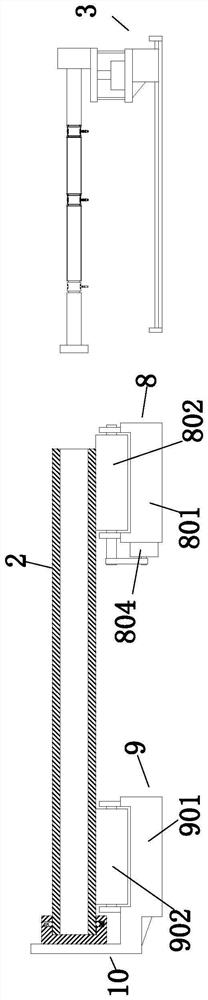
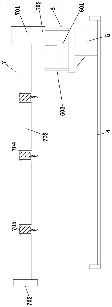
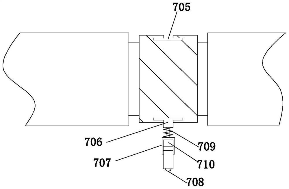
[0019] Example. The inner wall surface cleaning device of steel pipe is composed of Figure 1 to Figure 5 As shown, it includes a steel pipe supporting rotating bracket 1, the steel pipe supporting rotating bracket 1 is provided with a steel pipe 2 to be cleaned, and a mobile cleaning mechanism 3 is provided on the side of the steel pipe supporting rotating bracket 1; the mobile cleaning mechanism 3 includes a ground rail 4, and the ground rail 4 is provided with a moving trolley 5, a lifting adjustment mechanism 6 is arranged above the moving trolley 5, and a cleaning assembly 7 is arranged on the lifting adjustment mechanism 6; the cleaning assembly 7 includes a cleaning drive motor 701, and the output end of the cleaning drive motor 701 is provided with a square The main throwing rod 702 of the pipe structure is provided with a polishing head 703 at the end of the main throwing rod 702 .
[0020] The main throwing rod 702 is also provided with a group of annular grooves 704 distributed side by side. The annular groove 704 is provided with an annular slide rail 705, the bottom of the annular slide rail 705 is provided with a slider 706, and a support frame 707 is provided below the slider 706. , a first ball 708 is arranged under the support frame 707 ; a spring 709 is also arranged between the support frame 707 and the slider 706 ; a counterweight 710 is also arranged on the support frame 707 .
[0021] The lift adjustment mechanism 6 includes a hydraulic cylinder 601 located above the mobile trolley 5 , a placement platform 602 is provided at the output end of the hydraulic cylinder 601 , and a guide rod 603 is provided between the placement platform 602 and the movable trolley 5 .
[0022] The steel pipe supporting rotating bracket 1 includes an active rotating base 8 and a driven rotating base 9 distributed side by side, and the steel pipe 2 to be cleaned is located between the active rotating base 8 and the driven rotating base 9; the driven rotating base The seat 9 includes a driven support 901. The driven support 901 is provided with two symmetrically distributed driven rollers 902. A driven rotation channel is provided between the two driven rollers 902, and a steel pipe is provided outside the driven rotation channel. Stopper 10 .
[0023] The active rotating base 8 includes an active support 801. The active support 801 is provided with a driving roller 802 and a follower roller 803. An active rotation channel is arranged between the driving roller 802 and the follower roller 803. The driving roller 802 is driven by A drive motor 804 is attached to the assembly.
[0024] The steel pipe blocking member 10 includes a baffle plate 101, a support sleeve 102 is arranged on the side of the baffle plate 101, a group of radial grooves 103 are evenly distributed on the inner wall surface of the support sleeve 102, and a reset is arranged in the radial groove 103. The spring 104 and the second ball 105, the inner end of the radial groove 103 is provided with an anti-disconnection limit plate 106 matched with the ball 105.
[0025] The mobile trolley has its own drive device and can move along the ground rail.
[0026] There are openings on the anti-dropping limit support plate, which is convenient for the part of the ball to be exposed.
[0027] The cleaning process of the present invention: the steel pipe to be cleaned is placed on the steel pipe rotating support, that is, the steel pipe to be cleaned is placed between the driven rotating channel and the active rotating channel, and the end of the steel pipe to be cleaned is inserted into the support sleeve, so that the steel pipe to be cleaned is The steel tube is in contact with the balls. Control the drive motor to work, drive the drive roller to rotate, the rotation of the drive roller will drive the steel pipe to be cleaned to rotate, and then drive the follower roller and the two driven rollers to rotate. At the same time, the lifting adjustment mechanism works to adjust the height of the cleaning component so that the polishing head matches the inner wall of the steel pipe to be cleaned, and then the trolley is moved to drive the main throwing rod and polishing head into the interior of the steel pipe, and the cleaning drive motor works and drives The polishing head and the main throwing rod rotate, and the throwing rod head is in even contact with the inner wall of the steel pipe to be cleaned, so as to clean the inner wall of the steel pipe. During the moving process, the first ball is in contact with the inner wall surface of the steel pipe to provide a support force for the main throwing rod, and will not rotate with the rotation of the main throwing rod.

PUM

no PUM

Description & Claims & Application Information

We can also present the details of the Description, Claims and Application information to help users get a comprehensive understanding of the technical details of the patent, such as background art, summary of invention, brief description of drawings, description of embodiments, and other original content. On the other hand, users can also determine the specific scope of protection of the technology through the list of claims; as well as understand the changes in the life cycle of the technology with the presentation of the patent timeline. Login to view more.

Similar technology patents

Pipeline welding device for exhaust pipe as motorcycle part

InactiveCN113601170AImprove work efficiencyGuaranteed smoothness
Owner:重庆市璧山区合成机械制造有限公司

Liquid cooling pipe laser cleaning and flow resistance testing compound machine

ActiveCN114130765AGuaranteed smoothnessIncrease productivity
Owner:安徽新富新能源科技股份有限公司

PCB positioning and conveying device based on correction and fixation

PendingCN114735437AGuaranteed smoothness
Owner:章琴

Rotary mold injection molding and cooling forming equipment for plastic particles

InactiveCN112454930AGuaranteed smoothnessAvoid drawing
Owner:薛芹

Universal drill bit for steel part machining

PendingCN112705761AIncreased breakage resistanceGuaranteed smoothness
Owner:阿斯图精密工具(上海)有限公司

Classification and recommendation of technical efficacy words

  • Guaranteed smoothness

Engine starting method of hybrid power vehicle power system

InactiveCN104842997AGuaranteed smoothnessThe driving torque of the whole vehicle is stable
Owner:BEIQI FOTON MOTOR CO LTD

Novel multifunctional bench drill

InactiveCN106424843AGuaranteed smoothnesskeep clean
Owner:杨娇仔

Automatic air purification device used for bus

InactiveCN108189646AGuaranteed smoothnessgood airflow
Owner:广东韩星健康家居科技有限公司

TM0-TE1 optical mode converter based on double-layer curve edge waveguide structure and optical device

ActiveCN114755757AImprove mode conversion efficiencyGuaranteed smoothness
Owner:ZHEJIANG LAB

Method for producing workpiece

InactiveCN1647887AGuaranteed smoothnessExtended service life
Owner:陈锡彩
Why Eureka
Try Eureka