Vertical and horizontal dual-purpose linkage processing machine tool
A machine tool, vertical and horizontal technology, applied in metal processing machinery parts, metal processing equipment, manufacturing tools and other directions, can solve problems such as low work efficiency, and achieve the effect of high work efficiency
- Summary
- Abstract
- Description
- Claims
- Application Information
AI Technical Summary
Problems solved by technology
Method used
Image

Examples
Embodiment 1
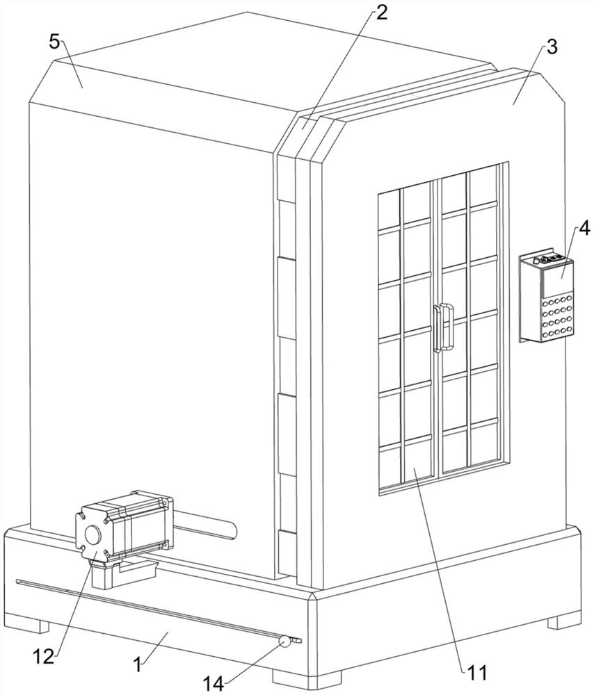
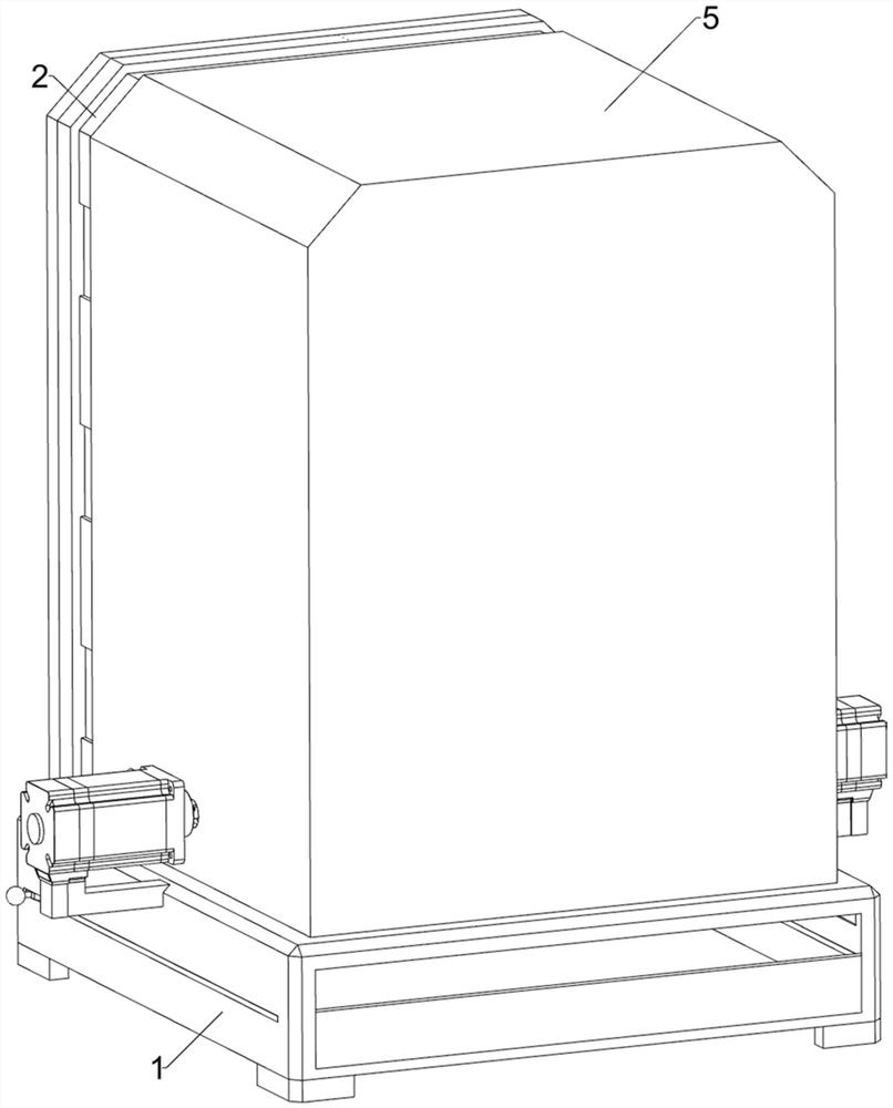
[0032] A vertical and horizontal dual-purpose linkage processing machine tool, including a frame body 1, a return shell 2, a return plate 3, a controller 4, a sliding frame 5, a lower hopper 6, a fixed seat 7, a swing frame 8, a processing spindle 9, Operating platform 10, closing mechanism 11 and driving mechanism 12, see Figure 1-Figure 4 As shown, the lower hopper 6 is pierced through the middle of the top of the frame body 1 through welding connection, and the lower hopper 6 can guide the iron filings. The top of the lower hopper 6 runs through the middle of the bottom of the return shell 2, and an operating platform 10 is installed between the lower right side of the front and rear sides of the return form shell 2, and the return form plate 3 is fixedly connected to the right side of the return form shell 2, and the return form plate 3 The outer bottom is fixedly connected with the right side of the outer top of the frame body 1, the controller 4 is installed on the rear...
Embodiment 2
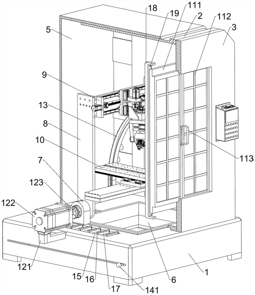
[0039] On the basis of Embodiment 1, an auxiliary mechanism 13 is also included. The auxiliary mechanism 13 includes a trigger lever 131, an arc frame 132, a fixed rod 133, a buffer block 134 and a first spring 135. Please refer to image 3 , Figure 5 , Figure 6 and Figure 7 As shown, three fixed rods 133 are installed on the left side of the lower part of the front and rear sides of the sliding frame 5 by welding, and there are fixed connections between the inner ends of the three fixed rods 133 on the front side and the inner ends of the three fixed rods 133 on the rear side. The arc frame 132, the right end of the arc frame 132 is located in the return shell 2, the bottom of the arc frame 132 is equipped with a first spring 135 by welding, the end of the first spring 135 is fixedly connected with a buffer block 134, the buffer block 134 is used for providing cushioning force, and front and rear both sides swing frame 8 outer surface tops all are installed with trigger ...
Embodiment 3
[0044] On the basis of Embodiment 1 and Embodiment 2, n-type plates 16 and contact rollers 17 are also included, please refer to image 3 and Figure 8 As shown, the outer bottom of the sliding frame 5 and the outer top of the frame body 1 are symmetrically opened with grooves 15 front and rear, and five n-type plates 16 are installed on the right side of the top of the upper groove 15 and connected by welding at even intervals. The contact roller 17 is connected in rotation between the front and rear sides of 16, and the contact roller 17 is located in the lower groove 15, and the contact roller 17 can guide the sliding frame 5.
[0045] Also includes u-shaped plate 18, scraper 19 and second spring 20, see image 3 , Figure 9 and Figure 10 As shown, the left side of the back-shaped plate 3 is symmetrically mounted with a u-shaped plate 18 by means of welding connection, the left side of the u-shaped plate 18 is embedded in a sliding connection with a scraper 19, and the ...
PUM
 Abstract
Description
Claims
Application Information
 - R&D
- Intellectual Property
- Life Sciences
- Materials
- Tech Scout
- Unparalleled Data Quality
- Higher Quality Content
- 60% Fewer Hallucinations
Browse by: Latest US Patents, China's latest patents, Technical Efficacy Thesaurus, Application Domain, Technology Topic, Popular Technical Reports.
© 2025 PatSnap. All rights reserved.Legal|Privacy policy|Modern Slavery Act Transparency Statement|Sitemap|About US| Contact US: help@patsnap.com