
Piezoelectric driving micro clamp with three-stage displacement amplification function and parallel clamping function

A technology of displacement amplification and piezoelectric drive, applied in the direction of clamps, manufacturing tools, etc., can solve the problems of large deformation of the clamp body, smaller working bandwidth of the micro-clamp, and lower natural frequency of the structure, and achieve the effect of high working bandwidth

Active Publication Date: 2022-03-25
SHANDONG UNIV
View PDF5 Cites 0 Cited by
  • Summary
  • Abstract
  • Description
  • Claims
  • Application Information

AI Technical Summary

Problems solved by technology

After reviewing literature and other materials by Guangfa, it is found that the displacement amplification ratio of the micro grippers designed at home and abroad basically does not exceed 30. In addition, if the parallel movement of the jaws can be realized, the gripping operation will be more reliable and easy, and at the same time, the high displacement amplification The ratio means that the deformation of the clamp body is larger, the structural stiffness becomes smaller, the natural frequency of the structure decreases, and the actual working bandwidth of the micro-clamp becomes smaller

Method used

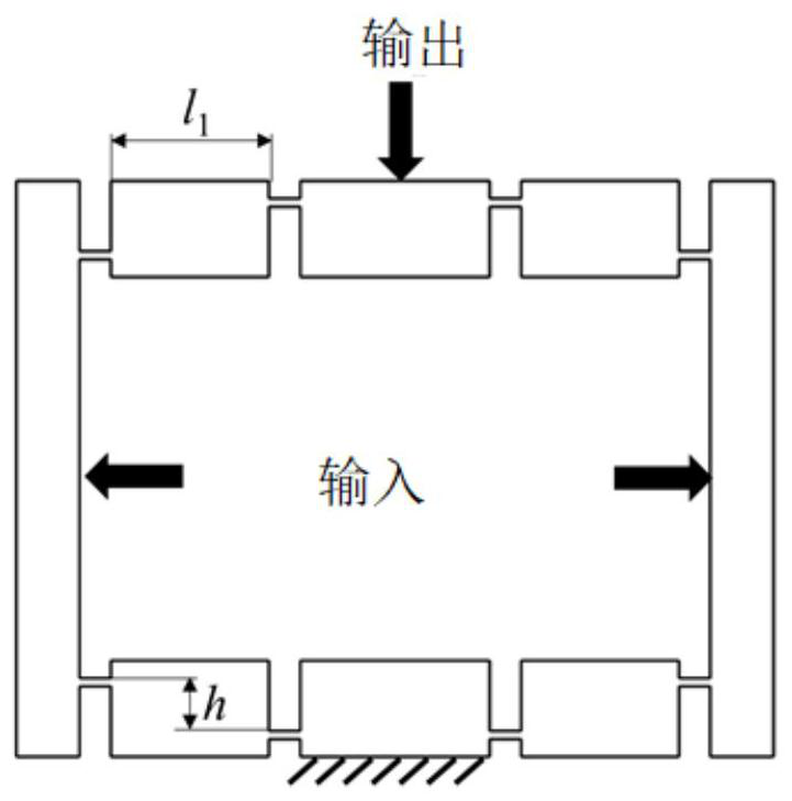
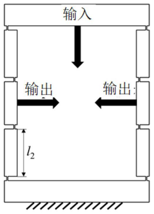
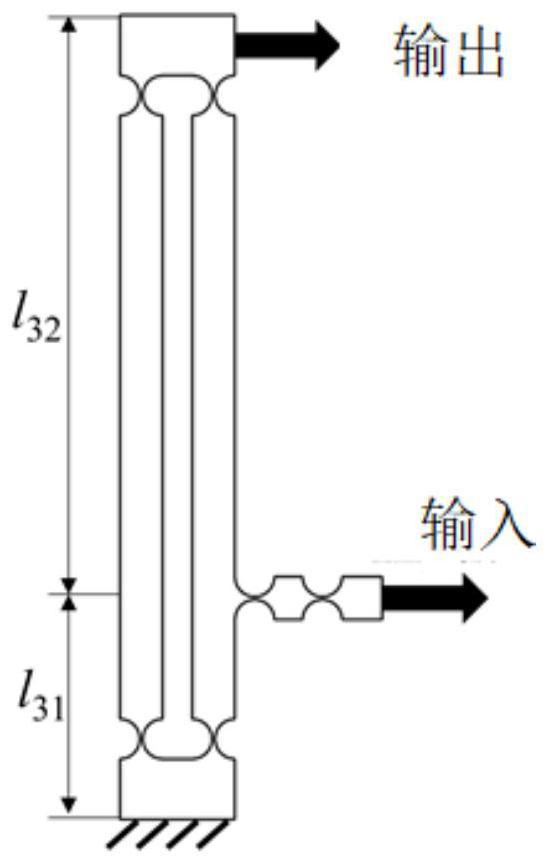

Image

  • Piezoelectric driving micro clamp with three-stage displacement amplification function and parallel clamping function
  • Piezoelectric driving micro clamp with three-stage displacement amplification function and parallel clamping function
  • Piezoelectric driving micro clamp with three-stage displacement amplification function and parallel clamping function

Examples


Embodiment Construction

[0024] It should be noted that the following detailed description is exemplary and intended to provide further explanation of the present invention. Unless defined otherwise, all technical and scientific terms used herein have the same meaning as commonly understood by one of ordinary skill in the art to which this invention belongs.

[0025] It should be noted that the terminology used here is only for describing specific embodiments, and is not intended to limit exemplary embodiments according to the present invention. As used herein, unless the invention clearly states otherwise, the singular form is also intended to include the plural form. In addition, it should also be understood that when the terms "comprising" and / or "comprising" are used in this specification, their Indicate the presence of features, steps, operations, means, components and / or combinations thereof;

[0026] This embodiment proposes a piezoelectric-driven micro-gripper with high amplification ratio, l...


PUM


Abstract

The invention discloses a piezoelectric driving micro clamp with three-stage displacement amplification and capable of realizing parallel clamping, which comprises a piezoelectric ceramic driving part, a first-stage displacement amplification mechanism, a second-stage displacement amplification mechanism and a third-stage displacement amplification mechanism, the piezoelectric ceramic driving part is connected with the first-stage displacement amplification mechanism, and the second-stage displacement amplification mechanism is connected with the third-stage displacement amplification mechanism. The first-stage displacement amplification mechanism is connected with the second-stage displacement amplification mechanism in series, the two output ends of the second-stage displacement amplification mechanism are each connected with one third-stage displacement amplification mechanism, the two third-stage displacement amplification mechanisms are connected in parallel, and the output ends of the two third-stage displacement amplification mechanisms are connected with the two clamping parts of the clamp respectively.

Description

technical field [0001] The invention relates to the field of piezoelectric drive, in particular to a piezoelectric-driven micro-clamp with a three-stage displacement amplification mechanism and capable of parallel clamping. Background technique [0002] In recent years, domestic scholars have designed micro-grippers based on different driving principles, such as piezoelectric (PZT) driving, electrostatic driving, thermal driving, electromagnetic driving, shape memory alloy driving, and pneumatic driving. Electrostatic drive is mainly realized by electrostatic comb drive, which has the advantages of high efficiency, fast response, low energy consumption, and simple structure. But it also has the obvious disadvantage of low clamping force. Thermal actuation takes the form of expansion induced by the use of conductive materials. The advantage is that the driving force is large, but it also has the disadvantage of slow response speed. In contrast, PZT-actuated microgrippers a...

Claims


Application Information

Patent Timeline
Patent Type & Authority Applications(China)
IPC IPC(8): B25B5/02B25B5/16
CPCB25B5/02B25B5/163
Inventor 马海峰郭中义陈杰刘战强宋清华
Owner SHANDONG UNIV
Learn More