Positioning mechanism and positioning method of cutter suction dredger

A technology of cutter suction dredger and positioning mechanism, which is applied in the direction of earth mover/shovel, mechanically driven excavator/dredger, ship parts, etc. Difficulty, limited layout area of ​​the three-cable positioning system, etc.

Active Publication Date: 2022-03-25
CCCC TDC ENVIRONMENTAL PROTECTION DREDGING
View PDF9 Cites 0 Cited by
  • Summary
  • Abstract
  • Description
  • Claims
  • Application Information

AI Technical Summary

Problems solved by technology

However, due to the requirements of special functions, self-propelled cutter suction dredgers have arranged a large number of large-scale engineering equipment and facilities on the upper deck or forecastle deck and the main deck area of ​​the tail, which greatly limits the layout area of ​​the three-cable positioning system. And for For the self-propelled cutter suction dredger with the working cutter head located at the tail, in order to reduce the resistance when the ship is sailing, the structure of the three-cable positioning system cannot be placed outside the ship’s side, but needs to be arranged inside the hull. Therefore, the cylinder of the three-cable positioning system The layout and design of the structure bring great difficulties

Method used


Image

  • Positioning mechanism and positioning method of cutter suction dredger
  • Positioning mechanism and positioning method of cutter suction dredger
  • Positioning mechanism and positioning method of cutter suction dredger

Examples


Embodiment Construction

[0022] Specific embodiments of the present invention will be described in detail below in conjunction with the accompanying drawings. It should be understood that the specific embodiments described here are only used to illustrate and explain the present invention, and are not intended to limit the present invention.

[0023] In the present invention, in the absence of a contrary description, the orientation words such as "upper, lower" and the like included in the term only represent the orientation of the term in the normal use state, or the common name understood by those skilled in the art, and should not be viewed as a limitation of this term.

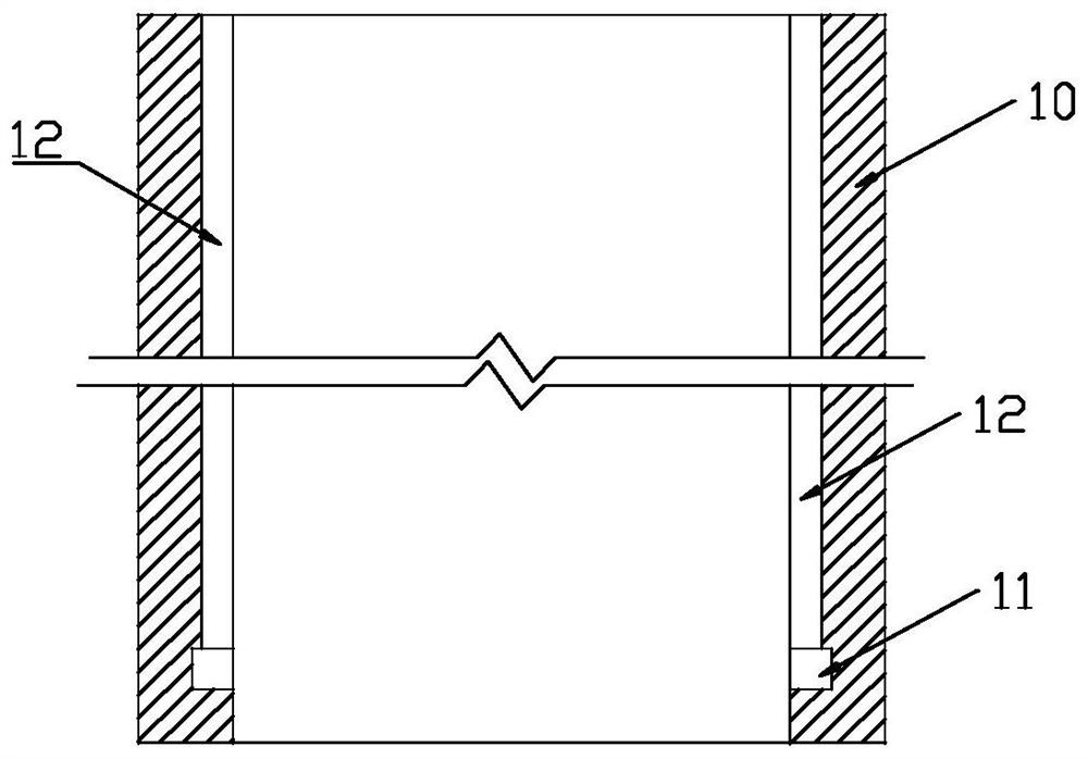
[0024] As mentioned earlier, combining figure 1 As shown, the present invention provides a positioning mechanism of a cutter suction dredger, the positioning mechanism includes an opening arranged in the hull and has a cylindrical structure as a whole, and a cylindrical structure 10 is arranged in the opening, so that The inner ...


PUM


Abstract

The invention relates to a cutter suction dredger, in particular to a cutter suction dredger positioning mechanism and a positioning method.The cutter suction dredger positioning mechanism comprises an open hole which is formed in a dredger body and is of a cylindrical structure on the whole, a barrel structure is arranged in the open hole, and an annular mounting groove is formed in the inner wall of the lower end of the barrel structure; a guide groove which is communicated with the annular mounting groove and extends upwards in the length direction of the barrel structure is formed above the annular mounting groove, an annular mounting frame is further arranged in the barrel structure and used for mounting a guide pulley, and a supporting block is arranged on the outer circle of the annular mounting frame. The supporting blocks and the guide grooves form sliding guide fit so that the annular installation frame can move to the annular installation groove, and after the supporting blocks rotate by a certain angle, the supporting blocks and the groove walls of the two sides of the annular installation groove form limiting fit. The problems that in the prior art, a barrel structure needs to be overall lifted out to guarantee the maintenance space, and hoisting is difficult due to the fact that the overall weight of the barrel structure is large are solved.

Description

technical field [0001] The invention relates to a cutter suction dredger, in particular to a positioning mechanism and a positioning method of the cutter suction dredger. Background technique [0002] With the increasing demand for sea reclamation projects and channel dredging projects, the construction and design of cutter suction dredgers are also developing towards large-scale and intelligent development. Construction plays an extremely important role. The working principle of the cutter suction dredger is to use the rotating reamer to loosen the soil at the bottom of the river or seabed, mix it with water to form mud, suck it into the pump body through the mud suction pipe, and send it to the mud discharge area through the mud discharge pipe. [0003] In the prior art, the most common application is to use steel pile positioning to realize the dredging positioning function, and realize the lifting and lowering of the main pile and the auxiliary pile, and the switching o...

Claims


Application Information

Patent Timeline
Patent Type & Authority Applications(China)
IPC IPC(8): B63B21/50E02F3/88
CPCB63B21/50E02F3/885
Inventor 刘万龙孙合臣王国伟张宁
Owner CCCC TDC ENVIRONMENTAL PROTECTION DREDGING
Why Eureka
Try Eureka