Rainwater dispatching and flood storage system for sponge city

A sponge city and rainwater technology, applied in waterway systems, sewage discharge, water supply devices, etc., can solve the problems of underutilized drainage capacity of rainwater pipe network, difficulty in fully utilizing storage capacity, and limited mitigation effect of urban waterlogging, etc. Achieve the effect of improving the ability of extreme heavy rain, wide range of use, and reducing urban waterlogging

Pending Publication Date: 2022-03-25
FLOWER KING ECO ENG CO LTD
View PDF0 Cites 0 Cited by
  • Summary
  • Abstract
  • Description
  • Claims
  • Application Information

AI Technical Summary

Problems solved by technology

In order to achieve the purpose of rainwater utilization while completing stormwater control, natural lakes are often used in engineering construction, or rainwater storage facilities such as rainwater storage tanks and rainwater barrels are artificially set up, and part of the rainwater is retained for later recycling; The real-time scheduling of some rainwater storage facilities often relies on the experience analysis of engineering designers, lacking scientific and reliable scheduling and operation methods
Under such a background, the space of rainwater regulation and storage facilities is often filled at the beginning of rainfall, and its regulation and storage volume is difficult to be fully utilized. The mitigation effect on urban waterlogging is very limited, and the drainage capacity of the rainwater pipe network is not fully utilized. In addition, the initial rainfall generally has high pollutant content, and the rainfall runoff at the initial stage of storage and storage will also lead to a sharp increase in the pollutant content of the stored water

Method used


Image

  • Rainwater dispatching and flood storage system for sponge city
  • Rainwater dispatching and flood storage system for sponge city
  • Rainwater dispatching and flood storage system for sponge city

Examples


Embodiment Construction

[0020] In order to deepen the understanding of the present invention, the present invention will be further described below in conjunction with the embodiments and accompanying drawings. The embodiments are only used to explain the present invention and do not constitute a limitation to the protection scope of the present invention.

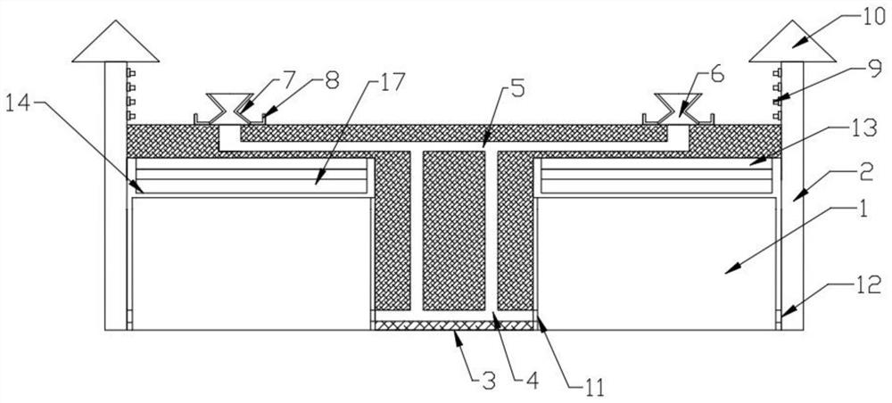
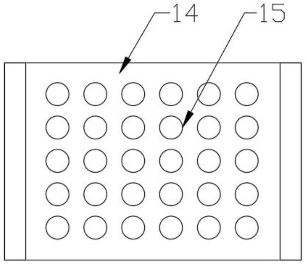
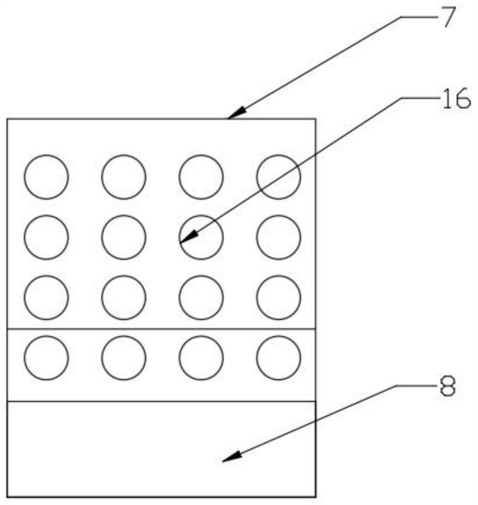
[0021] Such as Figure 1~3 As shown, the rainwater dispatching and flood storage system for sponge city includes flood storage tank 1, overflow tank 2, water inlet tank 3, water inlet pipe 4, connecting pipe 5, water inlet device 6, filter water inlet plate 7, miscellaneous storage area 8, Water outlet 9, rain cover 10, water inlet 11, overflow pipe 12, large gravel layer 13, water inlet plate 14, water permeable opening 15, water inlet hole 16.

[0022] The rainwater dispatching and flood storage system used in the sponge city includes a flood storage tank group. The highest point of the flood storage tank group is set lower than the soil layer....


PUM


Abstract

The rainwater dispatching and flood storage system for the sponge city comprises a flood storage pool set, the highest point of the flood storage pool set is lower than a soil layer, the flood storage pool set comprises two flood storage pools, a water inlet groove is formed between the two flood storage pools, each flood storage pool comprises a main body and a water inlet plate, and a groove is formed in the upper surface of each water inlet plate; the two water inlets are connected through a water inlet pipe, water inlet devices are arranged at the two ends of the connecting pipe and located on the upper surface of the soil layer, overflow boxes are arranged on the left side and the right side of the flood storage pool set, the overflow boxes are connected with the flood storage pools through overflow pipes, and the overflow pipes are connected with the overflow boxes. A plurality of water outlets are formed in the inner wall of the upper section of the overflow box, and a rain shielding cover is arranged at the top of the overflow box. The sponge city rainwater treatment device has the multiple functions of rainwater collection, rainwater filtration, rainwater purification, rainwater dispatching, secondary utilization and the like, the application range is wider, use is more convenient and faster, and the sponge city rainwater treatment effect is enhanced.

Description

technical field [0001] The invention relates to a rainwater dispatching and flood storage system for a sponge city. Background technique [0002] In recent years, rainwater control and rainwater utilization have received more and more attention in the planning and design of municipal drainage facilities and architectural design. In order to achieve the purpose of rainwater utilization while completing stormwater control, natural lakes are often used in engineering construction, or rainwater storage facilities such as rainwater storage tanks and rainwater barrels are artificially set up, and part of the rainwater is retained for later recycling; The real-time scheduling of some rainwater storage facilities often relies on the experience analysis of engineering designers, lacking scientific and reliable scheduling and operation methods. Under such a background, the space of rainwater regulation and storage facilities is often filled at the beginning of rainfall, and its regul...

Claims


Application Information

Patent Timeline
Patent Type & Authority Applications(China)
IPC IPC(8): E03F1/00E03F5/10E03F5/14E03F5/04
CPCE03F1/00E03F5/10E03F5/14E03F5/04E03F5/101
Inventor 肖姣君贺伟涛尹小琴尹小香胡晓轶
Owner FLOWER KING ECO ENG CO LTD
Why Eureka
Try Eureka