
High-speed precise gear transmission device

A gear transmission and precision technology, which is applied in the direction of gear transmission, transmission, transmission parts, etc., can solve the problems of inconvenience, inconvenient cooperation with reversing adjustment, and inability to realize power switching operations, etc., to achieve placement and connection, and convenient cooperation The effect of using

Inactive Publication Date: 2022-03-25
张足明
View PDF1 Cites 1 Cited by
  • Summary
  • Abstract
  • Description
  • Claims
  • Application Information

AI Technical Summary

Problems solved by technology

[0004] There is a phenomenon that it is inconvenient to carry out the coordination and adjustment of the inner end conversion, and the switching operation of the power cannot be realized, which will cause some inconvenience. At the same time, it is also inconvenient to carry out the external coordination and reversing adjustment, which needs to be improved

Method used


Image

  • High-speed precise gear transmission device
  • High-speed precise gear transmission device
  • High-speed precise gear transmission device

Examples


Embodiment 1

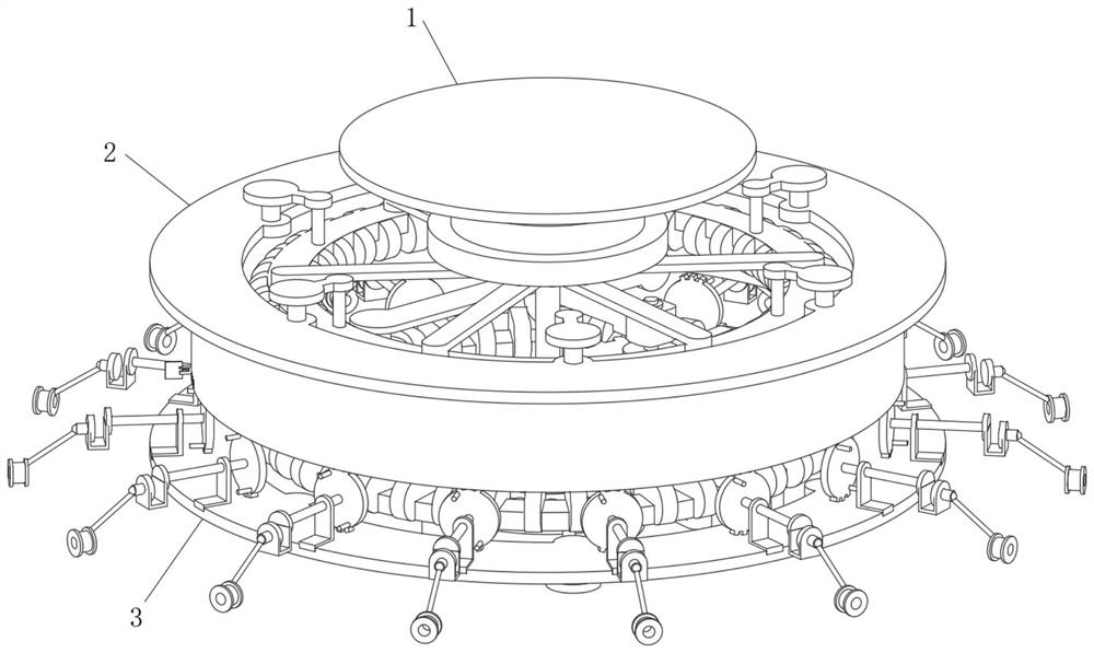
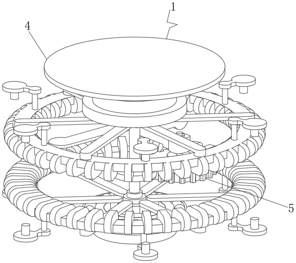
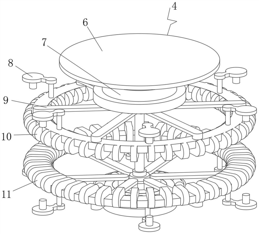
[0032] see Figure 1-7 , the present invention provides a technical solution: a high-speed precision gear transmission device, including a gear matching device 1, the side end position of the gear matching device 1 is fixedly connected with an adjustment device 2, and the bottom end position of the adjustment device 2 is connected with an external machining Device 3, by installing the gear matching device 1, the inner end of the gear matching device 1 is composed of a conductive part 4 and a steering part 5, wherein the conductive part 4 is used for supporting connection, which can realize the power transmission function, thereby driving the externally connected objects Carry out the rotation drive, and the setting of the steering part 5 adopts an adjustable setting, which can be regulated according to the demand, so as to realize the rotation control work of the first rotating toothed disc 10 and the second rotating toothed disc 11, which is convenient for the adjustment of th...

Embodiment 2

[0043] On the basis of Example 1, such as Figure 8 As shown, the bottom position of the external processing device 3 is fixedly sleeved with a holding plate 36 , the side end of the holding plate 36 is fixedly connected with a blocking plate 35 , and the upper end of the blocking plate 35 is provided with a second notch 34 .

[0044] Through the setting of the second notch 34, the barrier plate 35 and the holding plate 36, the placement of the processing solution can be realized, the production work with the external processing device 3 can be realized, and the overall production function can be realized, and through the second notch 34, It can facilitate the feeding work, and can cooperate with the external processing device 3 at the same time to realize the placement and connection of the upper end of the connecting seat cover 31 and the subsequent dismantling work.

[0045] Working principle: When work is required, the user sets the gear matching device 1, the adjustment d...


PUM


Abstract

The invention discloses a high-speed precise gear transmission device which comprises a gear matching device, an adjusting device is fixedly connected to the side end of the gear matching device, an outer machining device is connected to the bottom end of the adjusting device in a contact mode, and the gear matching device comprises a conduction component and a steering component. The transmission component is arranged at the center position of the inner end of the gear matching device, the steering component is connected to the middle position of the transmission component in an overturning and meshing mode, the transmission component comprises a top plate frame, a spring seat, a placing frame, a side connecting frame, a first rotating fluted disc and a second rotating fluted disc, and the top plate frame is arranged at the top position of the inner end of the transmission component. The lower end of the top plate frame is elastically connected with a spring seat, and the lower end of the spring seat is connected with a side connecting frame in a sleeved mode. According to the high-speed precise gear transmission device, through the arrangement of the gear matching device, the purpose of inner end matching production is achieved.

Description

technical field [0001] The invention relates to the technical field of gear transmission equipment, in particular to a high-speed precision gear transmission device. Background technique [0002] According to Chinese Patent No. CN201810178225.4, the present invention discloses a planetary gear transmission, which includes a cylindrical shell and a planetary wheel, a sun gear, and an inner ring gear located in the shell, and the planetary gear transmission also includes a set The outer cover plate and the inner transparent plate on the end cover of the shell, the outer cover plate is provided with a hollow arc, the center of the hollow arc is located at the rotation center of the planetary gear transmission, and the inner transparent plate is located between the outer cover plate and the end cover , and the inner transparent plate completely covers the hollow arc, and there is an oil level indicating cavity for observing the oil level between the inner transparent plate and t...

Claims


Application Information

Patent Timeline
Patent Type & Authority Applications(China)
IPC IPC(8): F16H3/02F16H57/02B65G29/00B65G47/248
CPCF16H3/001F16H3/02B65G29/00B65G47/248F16H2057/02013
Inventor 张足明
Owner 张足明
Learn More