Projection device

A projection device and installation surface technology, applied in projection devices, optics, instruments, etc., can solve problems such as poor resolution, assembly errors, and inconvenient use of micro-projectors, so as to improve visual experience, reduce assembly errors, and facilitate operation Effect

Pending Publication Date: 2022-03-25
GOERTEK OPTICAL TECH CO LTD
View PDF0 Cites 0 Cited by
  • Summary
  • Abstract
  • Description
  • Claims
  • Application Information

AI Technical Summary

Problems solved by technology

However, since the lens of the lighting system and the lens of the lens system are very prone to assembly errors during the assembly process, the assembled micro-projector often has poor resolution and projected image offset, which is very inconvenient to use

Method used


Image

  • Projection device
  • Projection device
  • Projection device

Examples


Embodiment Construction

[0032] Various exemplary embodiments of the present application will now be described in detail with reference to the accompanying drawings. It should be noted that the relative arrangements of components and steps, numerical expressions and numerical values ​​set forth in these embodiments do not limit the scope of the present application unless specifically stated otherwise.

[0033] Embodiments of the present application will be described in detail below, examples of which are shown in the drawings, in which the same or similar reference numerals denote the same or similar elements or elements having the same or similar functions throughout. The embodiments described below by referring to the figures are exemplary, and are only for explaining the present application, and should not be construed as limiting the present application. Based on the embodiments in this application, all other embodiments obtained by persons of ordinary skill in the art without creative efforts fal...


PUM


Abstract

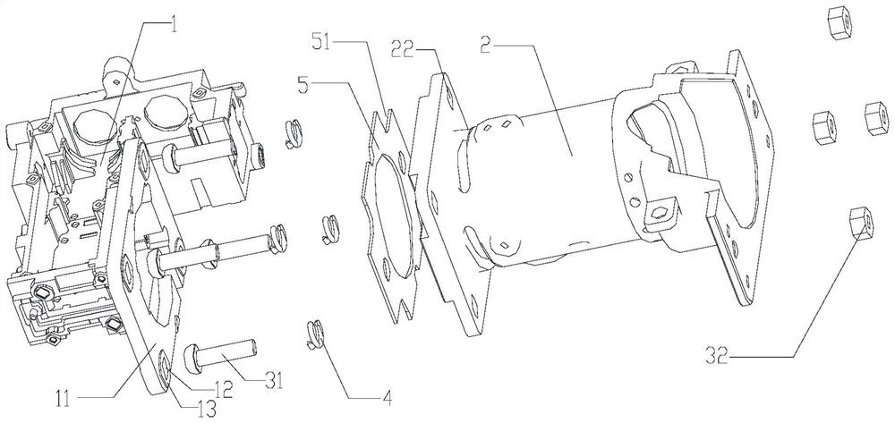
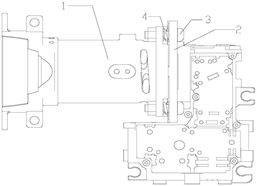
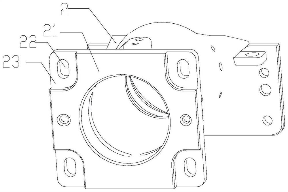
The embodiment of the invention discloses a projection device. The projection device comprises a ray machine main body, a lens assembly, a fastener and a spring, the ray machine main body is provided with a first mounting surface, and a first through hole is formed in the first mounting surface; the lens assembly is detachably connected with the ray machine main body; the lens assembly is provided with a second mounting surface, and a second through hole is formed in the second mounting surface; the maximum width of the cross section of the fastener is smaller than the minimum aperture of the cross section of the second through hole, and the fastener can move in the second through hole. One technical effect of the embodiment of the invention is that the structural design is reasonable, the position of the lens assembly relative to the ray machine main body can be effectively adjusted, the assembly error is reduced, and the picture quality of a projected image is improved.

Description

technical field [0001] The present application belongs to the technical field of electronic products, and in particular, the present application relates to a projection device. Background technique [0002] With the development of projection technology, the development direction of projectors is gradually moving towards the direction of miniaturization and portability, thus the miniature projector was born. The micro projector is closer to life and entertainment. The working principle of the micro projector is to emit light from the light source. Through a series of optical lighting systems, the light from the light source is evenly irradiated on the display chip, and the signal passes through the circuit system on the display chip. The color scale and gray scale are realized, and the image is displayed. After that, the projection lens on the front end of the projection will enlarge and project the image on the display chip to the corresponding screen. [0003] The current ...

Claims


Application Information

Patent Timeline
Patent Type & Authority Applications(China)
IPC IPC(8): G03B21/14
CPCG03B21/14
Inventor 张强尹群陶淑林
Owner GOERTEK OPTICAL TECH CO LTD
Why Eureka
Try Eureka