
I2C bus verification method and verification system

A bus verification and verification system technology, applied in the field of I2C bus verification methods and verification systems, can solve the problems of no detection function, single timing parameter settings, and inability to change, and achieve the effect of improving reliability and improving reusability

Pending Publication Date: 2022-03-25
IPGOAL MICROELECTRONICS (SICHUAN) CO LTD
View PDF0 Cites 0 Cited by
  • Summary
  • Abstract
  • Description
  • Claims
  • Application Information

AI Technical Summary

Problems solved by technology

[0008] It can be seen from Table 1 and Table 2 above that when the I2C bus is in different operating modes standard-mode, fast-mode or high-speed mode (hs-mode), the corresponding timing parameters are different, so The reusability of the verification environment is not high
The traditional method does not automatically detect the timing. When performing gate-level simulation (post-simulation), we need to care about the timing problem. The traditional method does not have the detection function in different modes; in actual situations, the jitter and duty of the SCL clock signal Different ratios may also affect the communication of the protocol
[0009] In the current verification process, the timing parameter settings are simplified and cannot be changed. When I2C is in different modes (standard-mode, fast-mode or hs-mode), the parameters need to be manually modified again, because the changes of these parameters will affect the signal. The modification of the drive output is equivalent to rebuilding the environment; there is no timing detection module, and the gate-level simulation (post-simulation) is generally more concerned about the timing detection, and the establishment and hold time will not be considered in the pre-simulation; in addition, the SCL signal occupies The duty cycle is uncontrollable, and it is impossible to simulate problems such as SCL clock jitter in actual situations, because many designs of SCL signals have a 50% duty cycle, and there is no explicit regulation, so basically no one will notice, and the SCL clock jitter In many cases, the designer will not pay attention to the problem during the pre-simulation, but this does not mean that it has no impact on the actual chip. Sometimes the chip may not violate the timing, but it still cannot work normally under a certain limit duty cycle, affecting the entire The running stability of the chip

Method used


Image

  • I2C bus verification method and verification system
  • I2C bus verification method and verification system
  • I2C bus verification method and verification system

Examples


Embodiment Construction

[0031] Embodiments of the present invention will now be described with reference to the drawings, in which like reference numerals represent like elements. As mentioned above, the present invention provides an I2C bus verification method and verification system. The I2C bus verification method and verification system of the present invention can dynamically adjust the duty cycle of the clock signal, satisfying a wider range of application tests, and greatly Improve the reliability of verification.

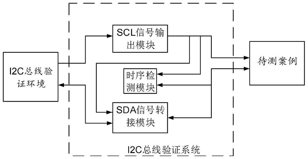
[0032] Please refer to figure 1 , figure 1 It is a structural block diagram of the I2C bus verification system of the present invention. As shown in the figure, the verification system of the I2C bus of the present invention is arranged between the I2C bus verification environment and the case to be tested, and a timing parameter table conforming to the I2C bus specification is arranged in the verification system, and the timing parameter table is as follows As shown in Table 1 ...


PUM


Abstract

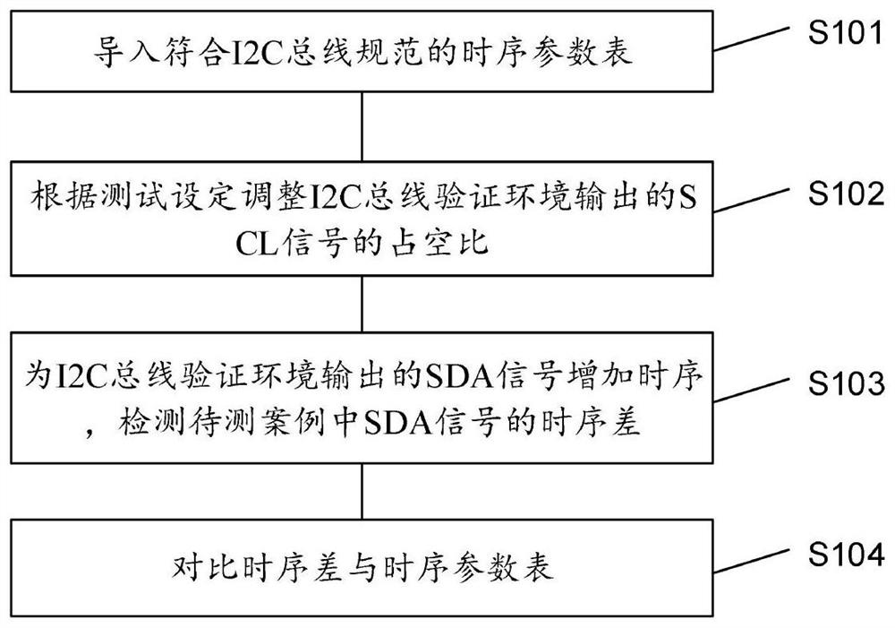
The invention discloses an I2C bus verification method applied to the verification system. The I2C bus verification method comprises the following steps of: a, importing a time sequence parameter table conforming to I2C bus specifications; b, adjusting the duty ratio of the SCL signal output by the I2C bus verification environment according to the test setting; c, increasing a time sequence for the SDA signal output by the I2C bus verification environment, and detecting a time sequence difference of the SDA signal in the to-be-detected case; and d, comparing the time sequence difference with the time sequence parameter table. Correspondingly, the invention further discloses a verification system of the I2C bus. According to the I2C bus verification method and verification system, the duty ratio of the clock signal can be dynamically adjusted, wider application tests are met, and the verification reliability is greatly improved.

Description

technical field [0001] The invention relates to the field of verification of bus interface technology, in particular to an I2C bus verification method and verification system. Background technique [0002] The I2C bus is a two-wire serial protocol. In the traditional verification process, the generation of the stimulus is often based on the clock signal edge of the SCL (the clock signal of the I2C bus) generated by the host to determine when to send or sample the SDA (the clock signal of the I2C bus). Data signal) data signal, so as to realize protocol communication. However, in real situations, the timing is often not so ideal. The SDA data signal and the SCL clock signal have setup and hold times, and the I2C bus is in different working modes: standard-mode, fast-mode or high-speed mode. (hs-mode), the corresponding timing parameter tables conforming to the I2C bus specification (THEI2C-BUS SPECIFICATION) are shown in Table 1 and Table 2: [0003] [0004] Table 1 ...

Claims


Application Information

Patent Timeline
Patent Type & Authority Applications(China)
IPC IPC(8): G06F11/22
CPCG06F11/221G06F11/2273
Inventor 周春燕
Owner IPGOAL MICROELECTRONICS (SICHUAN) CO LTD
Learn More