
Visualization method and system for automatic layout mapping

An automatic layout and graphing technology, applied in the field of data processing, can solve problems such as inconsistent view styles of the same type, panoramic display of views, and poor legibility of the structure, so as to improve the efficiency of view drawing, realize multiple perspectives, improve accuracy and completeness sexual effect

Pending Publication Date: 2022-03-25
CHINA CONSTRUCTION BANK
View PDF0 Cites 2 Cited by
  • Summary
  • Abstract
  • Description
  • Claims
  • Application Information

AI Technical Summary

Problems solved by technology

[0004] First, with the increase in system size and the complexity of internal relationships, it is difficult to quickly and accurately identify and draw all the components and relationships that need to be drawn manually, resulting in low efficiency in the drawing process of the architecture view; second, the rapid development of business, Rapid changes in the IT system are required to cope with the changes. After the system changes, the data of the technical architecture view should also be changed synchronously. However, the manually drawn view needs to be manually updated by the architect, which cannot guarantee the timeliness of data update, accuracy and completeness of the technical architecture view data. The third is that different architects have inconsistent understanding of architecture design, and each person draws different architecture views. There are problems of inconsistent view display specifications, inconsistent styles, poor legibility of architecture, and poor sharing of architecture views.
[0005] Therefore, the artificial view rendering efficiency of the prior art is low, the data update is not timely, the style of the same view is not uniform, and the viewing angle is single, and the view cannot be displayed in a panoramic view.

Method used


Image

  • Visualization method and system for automatic layout mapping
  • Visualization method and system for automatic layout mapping
  • Visualization method and system for automatic layout mapping

Examples


Embodiment Construction

[0067] The following will clearly and completely describe the technical solutions in the embodiments of the application with reference to the drawings in the embodiments of the application. Apparently, the described embodiments are only some of the embodiments of the application, not all of them. Based on the embodiments in this application, all other embodiments obtained by persons of ordinary skill in the art without making creative efforts belong to the scope of protection of this application.

[0068] In this application, the term "comprises", "comprises" or any other variation thereof is intended to cover a non-exclusive inclusion such that a process, method, article, or apparatus comprising a set of elements includes not only those elements, but also includes none. other elements specifically listed, or also include elements inherent in such a process, method, article, or apparatus. Without further limitations, an element defined by the phrase "comprising a ..." does not...


PUM


Abstract

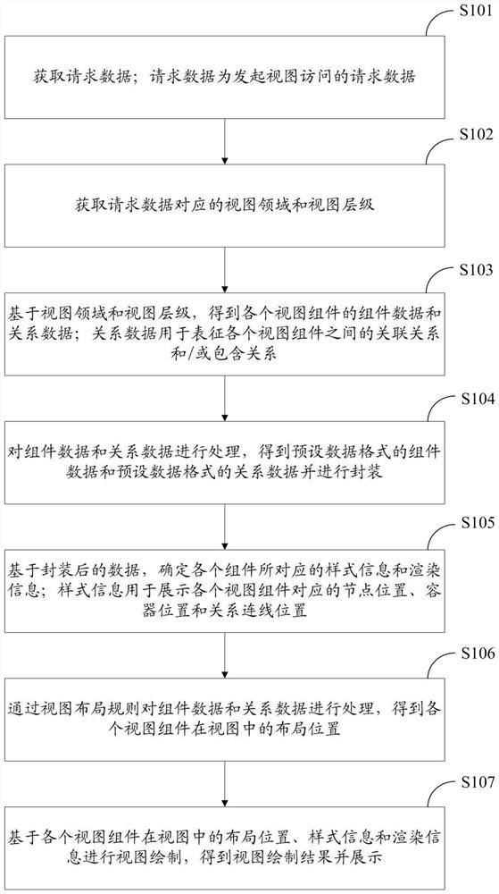
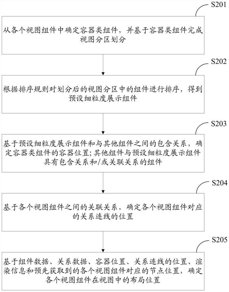
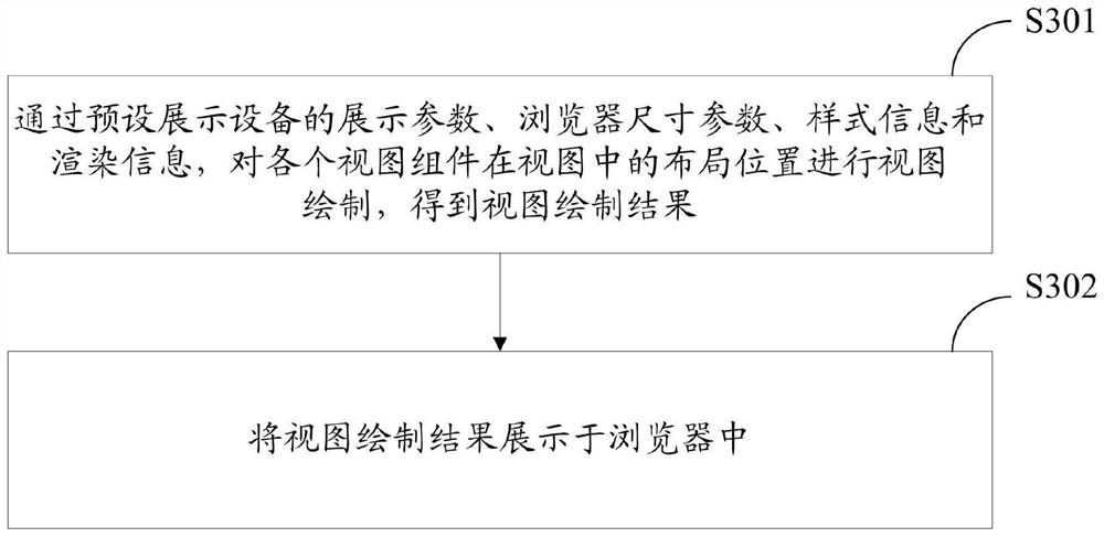
The invention discloses a visualization method and system for automatic layout mapping, and the method comprises the steps: obtaining the component data and relation data of each view component through a view field and a view hierarchy corresponding to request data, and determining the style information and rendering information corresponding to each component, and processing the component data and the relational data through a view layout rule to obtain a layout position of each view component in the view, performing view drawing based on the layout positions, the style information and the rendering information to obtain a view drawing result, and displaying the view drawing result. According to the technical scheme, manual view drawing is not needed, the view drawing efficiency is improved, the architecture view data are obtained and updated in real time, the functions of real-time drawing, automatic layout, mapping display and the like of various types of technical architecture views are achieved in the browser, unification of similar view styles of technical architectures is achieved, the accuracy and integrity of the technical architecture view data are improved, and the technical architecture view data can be displayed in real time. And multi-view and multi-level automatic mapping display of the technical architecture view is realized.

Description

technical field [0001] The present application relates to the technical field of data processing, and more specifically, to a visualization method and system for automatic layout and graph formation. Background technique [0002] The technical architecture view is a graphical display of the IT system technical architecture from different perspectives, mainly including system view, storage view, network view, resource pool view, computer room environment view, etc. The technical architecture view is a graphical and visual expression of the components contained in the system and its infrastructure and the relationship between components. [0003] The current traditional technical architecture Figure 1 Generally, architects use Visio, PPT and other tools to manually design and draw. The problems of this method are as follows: [0004] First, with the increase in system size and the complexity of internal relationships, it is difficult to quickly and accurately identify and dr...

Claims


Application Information

Patent Timeline
Patent Type & Authority Applications(China)
IPC IPC(8): G06F16/904G06F16/957
CPCG06F16/904G06F16/957
Inventor 侯岳李世宁杨晓勤
Owner CHINA CONSTRUCTION BANK
Learn More