Eureka AIR delivers breakthrough ideas for toughest innovation challenges, trusted by R&D personnel around the world.

An optical camera acquisition control system and method

A control system and camera technology, applied in closed-circuit television systems, TV system components, image communications, etc., can solve problems such as unreasonable use of resources, increased resource costs, increased work difficulty, etc., to improve the efficiency of image acquisition, improve The effect of speed and equipment cost saving

Active Publication Date: 2022-05-27
深圳市雷影光电科技有限公司
View PDF0 Cites 0 Cited by
  • Summary
  • Abstract
  • Description
  • Claims
  • Application Information

AI Technical Summary

Problems solved by technology

[0003] However, when controlling the optical camera to collect images in the prior art, there are the following problems: First, when the target is not a stationary object, multiple cameras are used to collect the image that needs to be collected in the target, but the number of cameras and the positions of the cameras cannot be reasonably allocated. The inability to obtain complete and effective information to the greatest extent, as well as the inability to rationally utilize resources, resulting in the disadvantages of increased resource costs; secondly, when the target moves, it is necessary to rotate the camera to collect information, and the existing technology needs to control each camera: Control the rotation angle of each camera, and it is impossible to realize the synchronous control of other cameras when controlling one camera, which increases the difficulty of work

Method used


Image

  • An optical camera acquisition control system and method
  • An optical camera acquisition control system and method

Examples


Embodiment 1

[0059] Embodiment 1: The ground of the shooting space is set as the reference plane, and the shooting space is bisected by m=3 vertical planes perpendicular to the reference plane. angle is , the area of ​​each vertical plane is s 平 =8, the unit is: square meter. It is simulated to set up an optical camera on the vertical line of each vertical plane. The vertical line passes through the center of each vertical plane, and the shooting angles of the three cameras are uniformly adjusted to , the imaging area of ​​the acquired camera is S=7, and when the target moves, the set of times the target appears on the imaging surface that needs to be collected is k={k1, k2, k3}={20, 5, 15}, according to the formula The set of effective coefficients of the image captured by the optical camera on the vertical lines of all vertical planes is obtained as W={W1, W2, W3}={0.42, 0.01, 0.28}, and the effective coefficient threshold is set as w=0.24, compare Wi and w, filter out the effective...

Embodiment 2

[0060]Embodiment 2: After the optical camera is set, three-dimensional modeling is performed on the shooting space, the target and the optical camera are positioned, and the set of camera position coordinates obtained is (x, y, z)={(x1, y1, z1), (x2, y2, z1)}, p=2, number the corresponding cameras, the number set is {1, 2}, simulate the camera to shoot the target, collect it into the historical data, when the target moves randomly once, Confirm the movement vector coordinates of the location of the information to be collected. The distance between the location of the information to be collected before and after the target moves randomly once is di=3, and the angle between the movement vector and the x-axis is , the average value of the difference between the rotation angle of the camera numbered 2 and the rotation angle of the camera numbered 1 every time the target moves is , the data that the target moves M=3 times is collected, and the set of camera rotation angles number...


PUM


Abstract

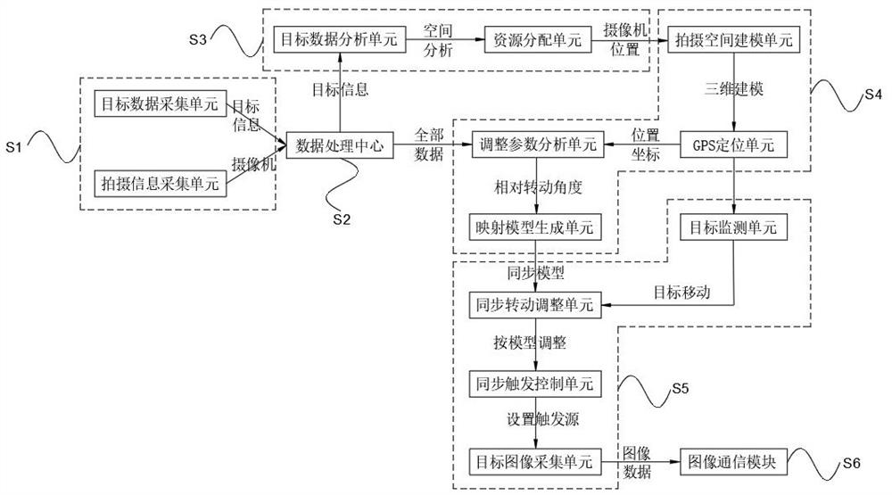
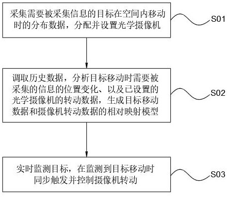
The invention discloses an optical camera acquisition control system and method, comprising: an initial information acquisition module, a data processing center, an acquisition resource planning module, an image acquisition planning module, an image acquisition control module and an image communication module, through which information to be acquired is acquired The mobile data of the target in the space, as well as the shooting data of the optical camera, store and manage all the collected data through the data processing center, allocate an appropriate number of optical cameras to collect images at the appropriate position through the collection resource planning module, and plan through the image collection The module generates a mapping model, and monitors the target through the image acquisition control module. When the target moves, set the same trigger source for the camera, rotate the camera synchronously according to the mapping model, control the image acquisition, and transmit the image through the image communication module, which improves the efficiency of image acquisition , which eases the difficulty of adjusting and controlling the camera.

Description

technical field [0001] The invention relates to the technical field of camera control, in particular to an optical camera acquisition control system and method. Background technique [0002] There are many types of optical cameras, but the basic principle of work is the same, which is to convert optical image signals into electrical signals to facilitate storage or transmission. With the development of science and technology, the application scope of optical cameras is more and more extensive. It has also been widely used: collecting images, and wirelessly transmitting images through the Internet to realize image collection and image communication, so as to detect abnormal operation in time and reduce losses; [0003] However, in the prior art, when controlling an optical camera to collect images, there are the following problems: First, when the target is not a stationary object, multiple cameras are used to collect the images contained in the target and need to be collecte...

Claims


Application Information

Patent Timeline
Patent Type & Authority Patents(China)
IPC IPC(8): H04N5/232H04N5/04H04N7/18
CPCH04N5/04H04N7/181H04N23/695
Inventor 刘瑞军陈宝锋
Owner 深圳市雷影光电科技有限公司
Why Eureka
Eureka Blog
Learn More