Rapid thickener

A thickener, fast technology, applied in separation methods, settling tanks, sustainable waste treatment, etc., can solve the problems of long discharge time, complex rake structure, large diameter of the thickener tank, etc., to improve dehydration speed and The effect of mass concentration, increasing the effective storage volume, and shortening the preparation time for discharging

Active Publication Date: 2022-03-29
CENT SOUTH UNIV +1
View PDF8 Cites 0 Cited by
  • Summary
  • Abstract
  • Description
  • Claims
  • Application Information

AI Technical Summary

Problems solved by technology

[0004] 1. The biggest feature of the deep cone thickener is the rake frame structure. The main function of the rake frame is to gather the slurry in the deep cone pool in the central barrel. The structure of the rake frame is complex, and the cost accounts for more than 50-80% of the entire thickener.
[0005] 2. The diameter of the tank of the thickener is large, and the thickness of the mud layer rises slowly. It takes a long time after the start-up for the thickness of the mud layer to meet the requirements of the stable discharge concentration of the bottom flow; The amount of sand is large and the discharge time is long, so it is difficult to realize instant stop
The drainage rod system continues to move in the mud layer, the tailings flocs are gradually destroyed, and the coarse and fine particles are separated. When the thickener cannot discharge continuously, the coarse-grained tailings settle rapidly and gather at the bottom of the thickener tank, and the thickener resumes discharge. After feeding, all of them are coarse-grained materials, which can easily cause pipe blockage; when there is no discharge for a long time, it is easy to cause a rake accident
[0007] 4. The inclination angle of the tank bottom of the thickener is small, generally below 30°, the grit cannot flow to the discharge port by itself, and is compressed by the upper mud layer for a long time, the grit at the bottom of the warehouse is easy to dehydrate and harden, reducing the storage capacity; Fluctuation and clogging of the sand discharge pipe
[0008] 5. The non-powered thickener mainly relies on the compression of the mud layer to increase the concentration of the sand discharged from the bottom of the thickener. There is no power device in the thickener, and the water contained in the tailings flocs cannot be discharged quickly. The discharged water has no rapid ascending channel. Slow thickening speed and low production efficiency

Method used


Image

  • Rapid thickener
  • Rapid thickener
  • Rapid thickener

Examples


Embodiment 1

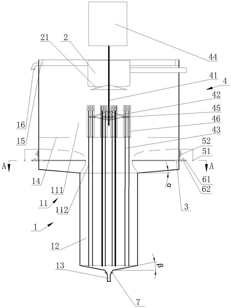
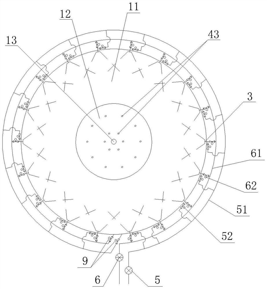
[0042] From figure 1 and figure 2 It can be seen that the rapid thickener in this embodiment includes a tank body 1, a feed box 2, a jet boost nozzle 3, a vibrating assembly 4, a pipeline pump 5 and a slurry pump 6,

[0043] The tank body 1 includes a separated transitional collection area 11, a compression vibration thickening area 12 and a sand discharge area 13 arranged coaxially and sequentially from top to bottom. The wall diameter is larger than the pool wall diameter of the compression vibration concentration zone 12, the pool wall diameter of the compression vibration concentration zone 12 is larger than the pool wall diameter of the sand release zone 13, and the separation transition collection zone 11 is divided into flocculation by the sand settling mud layer interface 14. Separation and clarification zone 111 and transition collection zone 112, a tank body overflow tank 15 is provided at the outer edge of the pool wall at the top of the flocculation separation an...

Embodiment 2

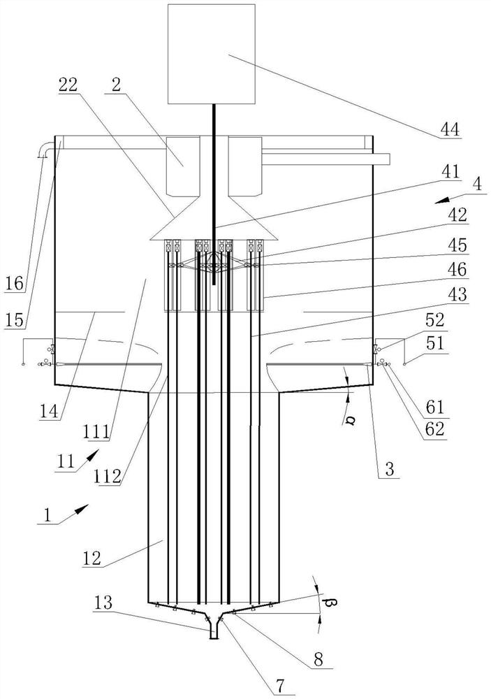
[0055] From image 3 It can be seen that compared with Embodiment 1, the difference of this embodiment is that a material distribution air guide hood 22 is provided at the center of the feed box, and the material distribution air guide 22 is connected to the bottom of the straight pipe section by a straight pipe section. Composed of round table sections, the top surface of the straight pipe section is arranged higher than the side wall of the feed box 2, the bottom surface of the round table section is arranged higher than the umbrella-shaped support 42, and the fixed shaft 41 is vertically arranged at the axis of the material distribution air guide cover 22; Several high-pressure air-driven and / or water-driven slurry-making activation nozzles 8 are arranged on the pool wall between the thickening zone 12 and the sand-discharging zone 13. On the wall of the pool, they are arranged staggered at intervals in a ring. When the slurry-making activation nozzle 8 adopts high-pressur...


PUM

PropertyMeasurementUnit
heightaaaaaaaaaa

Abstract

The invention discloses a rapid thickener which comprises a pool body and a feeding box hoisted in the center of the top of the pool body, and the pool body is divided into a separation transition material collecting area, a compression vibration concentration area and a sand discharging area from top to bottom. The diameter of the pool wall of the separation transition material collecting area, the diameter of the pool wall of the compression vibration concentration area and the diameter of the pool wall of the sand discharging area are sequentially reduced, a plurality of jet flow boosting nozzles are uniformly distributed at the bottom of the pool wall of the separation transition material collecting area in the circumferential direction, and a vibration assembly is arranged in the compression vibration concentration area. The thickness of a mud layer can be rapidly increased, and the preparation time for high-concentration underflow discharging of the thickener can be shortened; water seeping from the tailing slurry can quickly rise and fall off; the overflow runoff speed can be controlled, and muddy material carrying is prevented; a sand discharging funnel can be prevented from being formed, settled sand is eliminated, and the effective storage volume of the tank body is increased; a rake-free design is adopted, the structure is simpler, and no power is consumed in the sand setting process; and long-term storage is facilitated, and rapid concentration of low-concentration tailing slurry can be realized.

Description

technical field [0001] The invention relates to the technical field of resource utilization of mine solid waste, in particular to a fast thickener. Background technique [0002] The commonly used filling aggregate in metal mines is tailings (or tailings, including graded tailings and full tailings). The main filling process is to pump the tailings from the dressing plant with a low mass concentration (generally 10-20%, 40-45% when passing through a high-efficiency thickener) to the deep cone thickener of the filling preparation station, and flocculate and concentrate to a higher concentration (about 55-80%) and then discharged into the mixing system, mixed and stirred with the cementitious material (the cementitious material may not be added during non-cemented filling) to form a filling slurry that meets the requirements, and fill the pipeline through drilling and downhole, self-flowing or pumping Send to the place to be charged. [0003] According to the structure and op...

Claims


Application Information

Patent Timeline
Patent Type & Authority Applications(China)
IPC IPC(8): B01D21/08B01D21/24B01D21/28
CPCB01D21/08B01D21/2405B01D21/245B01D21/2472B01D21/283Y02W30/91
Inventor 赖伟周科平
Owner CENT SOUTH UNIV
Why Eureka
Try Eureka