Oxygen bomb replacement protection device

A protection device and oxygen bomb technology, applied in the installation device of container structure, gas/liquid distribution and storage, ship construction details, etc., can solve the problems of human body harm, high oxygenation pressure, safety accidents, etc., to protect the human body, Prevents spillage and improves safety

Active Publication Date: 2022-03-29
HUANENG PINGLIANG POWER GENERATION CO LTD
View PDF16 Cites 0 Cited by
  • Summary
  • Abstract
  • Description
  • Claims
  • Application Information

AI Technical Summary

Problems solved by technology

Therefore, after combustion, the oxygen filling pressure is high, and it is easy to cause safety accidents due to air leakage, and the oxygen leakage pressure is too high, and the gas products are unpleasant and harmful to the human body. Therefore, an oxygen bomb replacement protection device is urgently needed to make the oxygen bomb replacement process safe and efficient.

Method used


Image

  • Oxygen bomb replacement protection device
  • Oxygen bomb replacement protection device
  • Oxygen bomb replacement protection device

Examples


Embodiment 1

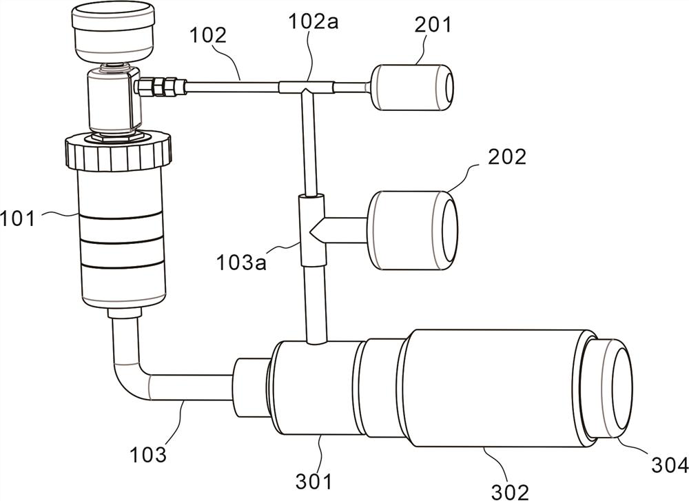
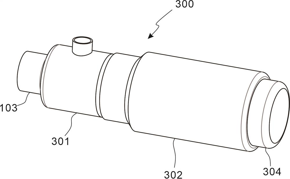
[0030] refer to Figure 1~2 For the first embodiment of the present invention, an oxygen bomb replacement protection device is provided, which includes an oxygen bomb assembly 100, including an oxygen bomb 101, an air inlet pipe 102 connected to the oxygen bomb 101, and an air outlet pipe 103; The air assembly 200 is connected with the oxygen bomb assembly 100, including the air inlet box 201 connected with the air inlet pipe 102, the liquid medium box 202 connected with the air inlet pipe 102; and the protection assembly 300, connected with the outlet pipe 102; The gas pipe 103 is connected, including a water storage area 301 , a pressure relief area 302 connected to the water storage area 301 , a valve core 303 arranged in the pressure relief area 302 , and a push rod 304 connected to the valve core 303 .

[0031] Among them, the oxygen bomb assembly 100 is an oxygen bomb experimental device, the ventilation assembly 200 inflates the inside of the oxygen bomb 101, dilutes th...

Embodiment 2

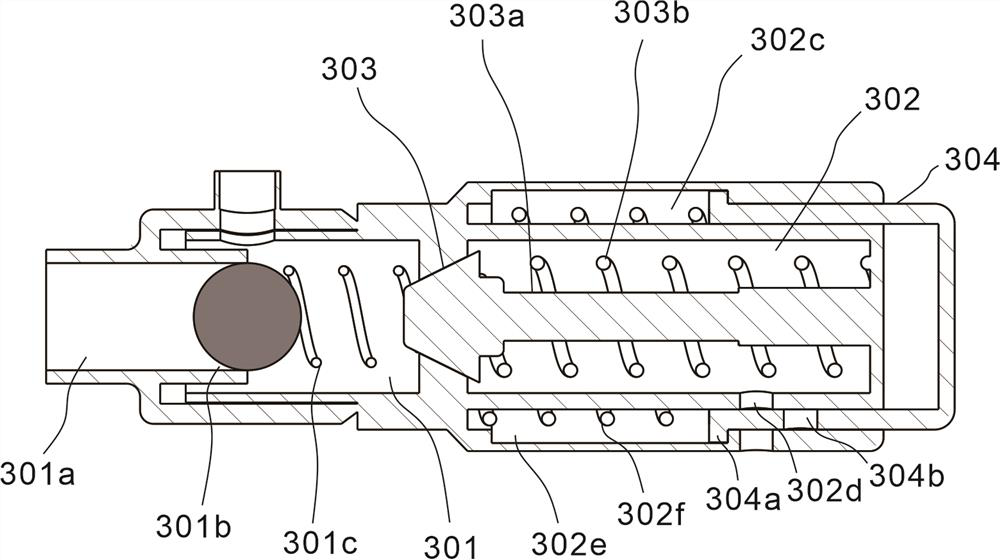
[0033] refer to Figure 2~4 , which is the second embodiment of the present invention. This embodiment is different from the first embodiment in that: the air intake pipe 102 is provided with a first one-way valve 102a, and the air intake box 201 passes through the air intake pipe 102 delivers gas to the oxygen bomb 101, the liquid medium tank 202 is also connected to the protection assembly 300, and the liquid medium tank 202 delivers liquid medium to the water storage area 301; the liquid medium tank 202 is connected to the water storage area A second one-way valve 103a is provided on the connecting pipeline of the zone 301 . The liquid medium box 202 keeps the inside of the water storage area 301 full of liquid medium, and the liquid medium box 202 stores a liquid medium, and the water storage area 301 absorbs the harmful gas produced by the combustion of the oxygen bomb 101; The air inlet box 201 delivers inert gas.

[0034] The water storage area 301 is connected to the...


PUM


Abstract

The invention discloses an oxygen bomb replacement protection device, which comprises an oxygen bomb assembly, an oxygen bomb, an air inlet pipe and an air outlet pipe, wherein the air inlet pipe and the air outlet pipe are connected with the oxygen bomb; the air exchange assembly is connected with the oxygen bomb assembly and comprises an air inlet box connected with the air inlet pipe and a liquid medium box connected with the air inlet pipe; the protection assembly is connected with the air outlet pipe and comprises a water storage area, a pressure relief area connected with the water storage area, a valve element arranged in the pressure relief area and a push rod connected with the valve element; according to the oxygen bomb replacement protection device, harmful gas in the oxygen bomb can be diluted, meanwhile, the harmful gas is absorbed through a liquid medium, pressure relief is conducted on the oxygen bomb through the protection device in the operation process, seamless connection can prevent the harmful gas from overflowing, meanwhile, the harmful gas can be discharged through the liquid medium, the human body is protected, and safety is improved.

Description

technical field [0001] The invention relates to the technical field of oxygen bombs, in particular to an oxygen bomb replacement protection device. Background technique [0002] The oxygen bomb calorimeter can be used to measure the calorific value of solid or liquid samples. It measures the heat generated by the combustion of the sample in a closed container (oxygen bomb) in an environment full of oxygen. The measured results are called combustion value and calorific value. , BTU, etc. [0003] Calorific value results have the significance of determining other values, can determine the quality of the sample, as a basis for calculating prices (such as coal), and can also obtain physiological (such as energy distribution in ecology, energy metabolism in animal nutrition research, etc.), physical and chemical conclusions. [0004] The oxygen bomb is an oxygen container made of heat-resistant and corrosion-resistant nickel-chromium alloy steel, which needs to be free from the...

Claims


Application Information

Patent Timeline
IPC IPC(8): B01D53/18F17C13/00F17C13/04
CPCB01D53/18F17C13/04F17C13/00F17C2225/0123F17C2205/0335
Inventor 贾怀丽张雨盖科成张斐王兴盛冯小丽马骏骁
Owner HUANENG PINGLIANG POWER GENERATION CO LTD
Why Eureka
Try Eureka