Steel structure connecting structure welding equipment

A technology for connecting structures and welding equipment, applied in welding equipment, auxiliary welding equipment, welding/cutting auxiliary equipment, etc., can solve problems such as affecting welding accuracy, prone to gaps, affecting welding efficiency, etc., to enhance welding effect, reduce The cost of labor and the effect of improving welding efficiency

Inactive Publication Date: 2022-03-29
东营硕明信息技术有限公司
View PDF0 Cites 2 Cited by
  • Summary
  • Abstract
  • Description
  • Claims
  • Application Information

AI Technical Summary

Problems solved by technology

[0002] The steel structure is mainly composed of steel beams, steel columns and steel trusses made of section steel and steel plates. It is widely used in large factories, venues, super high-rises and other fields. The components or parts are usually connected by welding, bolts or rivets. , when the general steel structure is processed, the steel column needs to be welded on the steel beam to make it welded into a cross-shaped connection structure (such as Figure 8 shown), and then install it on the steel structure in order to improve the strength of the steel structure. However, the following problems exist in the welding process of the steel structure: 1. In order to save processing costs, some small enterprises usually use manual operation The steel beam and the steel column are welded in the same way, so the welding efficiency is affected, and the steel column and the steel beam cannot be effectively fixed, so that the steel beam and the steel column are prone to shaking when welding, and then the gap is easy to appear, and the welding effect is affected
[0003] 2. During the welding process of steel beams and steel columns, most of the workers can only fix the steel beams and steel columns by hand. Working for a long time will cause fatigue to the workers, so it is easy to cause inclination between the steel beams and steel columns, and The position of the steel column cannot be adjusted accurately by hand-held means, which affects the accuracy of welding

Method used


Image

  • Steel structure connecting structure welding equipment
  • Steel structure connecting structure welding equipment
  • Steel structure connecting structure welding equipment

Examples


Embodiment Construction

[0029]The embodiments of the present invention will be described in detail below with reference to the accompanying drawings, but the present invention can be implemented in many different ways defined and covered by the claims.

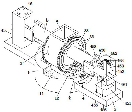
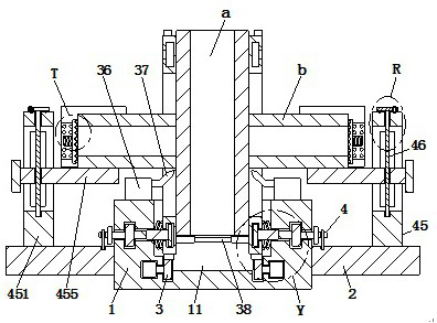
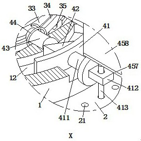
[0030] refer to Figure 1 to Figure 4 , a steel structure connection structure welding equipment, including a workbench 1, a supporting plate 2, a welding unit 3 and a clamping unit 4, the outer wall of the workbench 1 is fixedly fixed with the support plate 2 on the left and right sides, and the upper end of the workbench 1 is opened There is a semi-circular groove 11, and the inside of the workbench 1 is provided with fan-shaped grooves 12 symmetrically along the left and right sides of the semi-circle groove 11, and a fixed groove 13 is opened below the fan-shaped groove 12 inside the workbench 1, and the upper end of the supporting plate 2 is evenly opened along the circumferential direction of the workbench 1. A plurality of positioning holes 21...


PUM


Abstract

The invention relates to the technical field of steel structures, in particular to steel structure connecting structure welding equipment which comprises a workbench, bearing plates, a welding unit and a clamping unit, the bearing plates are fixedly installed on the outer wall of the workbench in a bilateral symmetry mode, the welding unit is arranged in the workbench, and the clamping unit is installed on the outer wall of the workbench; the steel structure welding device can solve the following problems existing during steel structure welding: some small enterprises generally adopt a manual operation mode to weld steel beams and steel columns in order to save the machining cost, so that the steel columns and the steel beams cannot be effectively fixed, the phenomenon of inclination between the steel beams and the steel columns is easily caused, and the welding quality is influenced. The welding effect is influenced; according to the welding device, circumferential welding treatment can be conducted on a steel beam and a steel column, the welding efficiency can be improved, the steel beam and the steel column can be clamped and limited correspondingly, and therefore the defects of gaps, deflection and the like during welding can be effectively avoided, and the welding effect can be enhanced.

Description

technical field [0001] The invention relates to the technical field of steel structures, in particular to welding equipment for connecting structures of steel structures. Background technique [0002] The steel structure is mainly composed of steel beams, steel columns and steel trusses made of section steel and steel plates. It is widely used in large factories, venues, super high-rises and other fields. The components or parts are usually connected by welding, bolts or rivets. , when the general steel structure is processed, the steel column needs to be welded on the steel beam to make it welded into a cross-shaped connection structure (such as Figure 8 shown), and then install it on the steel structure in order to improve the strength of the steel structure. However, the following problems exist in the welding process of the steel structure: 1. In order to save processing costs, some small enterprises usually use manual operation The steel beam and the steel column are w...

Claims


Application Information

Patent Timeline
Patent Type & Authority Applications(China)
IPC IPC(8): B23K37/00B23K37/047
CPCB23K37/00B23K37/047
Inventor 王玉洁
Owner 东营硕明信息技术有限公司
Why Eureka
Try Eureka