Embedded steel bar clamping groove positioning device

A technology of positioning device and pre-embedded steel bars, applied in structural elements, building components, building reinforcements, etc., can solve problems such as component spacing adjustment, and achieve the effects of preventing safety accidents, improving stability, and quickly adjusting

Inactive Publication Date: 2022-03-29
陕西建工第十四建设有限公司
View PDF0 Cites 0 Cited by
  • Summary
  • Abstract
  • Description
  • Claims
  • Application Information

AI Technical Summary

Problems solved by technology

[0003] The purpose of the present invention is to provide a pre-embedded steel bar slot positioning device to solve the problem in the above-mentioned background technology that the distance between positioning components cannot be adjusted

Method used


Image

  • Embedded steel bar clamping groove positioning device
  • Embedded steel bar clamping groove positioning device
  • Embedded steel bar clamping groove positioning device

Examples


Embodiment 1

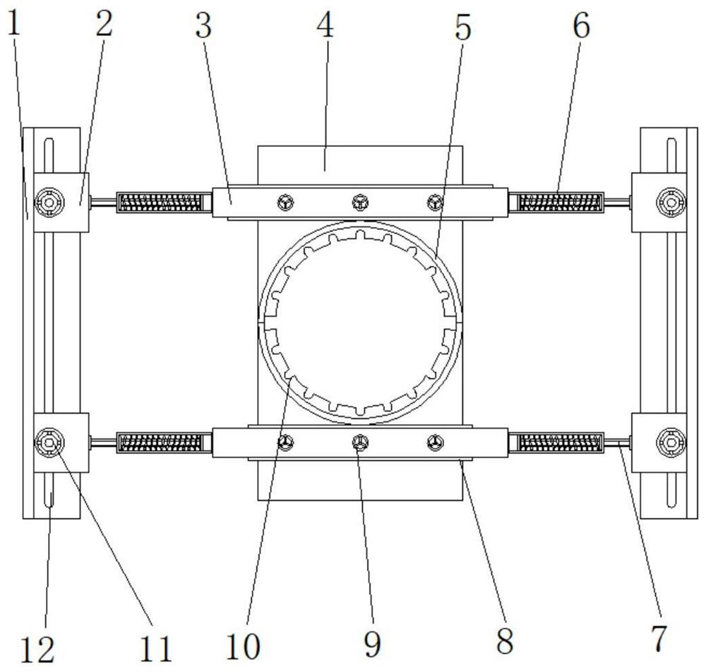
[0026] Example 1: See Figure 1-4 , a pre-embedded steel bar slot positioning device, including a positioning horizontal plate 3, two sets of positioning horizontal plates 3 are provided, and the two groups of positioning horizontal plates 3 are the same in size, and the two sides of the positioning horizontal plate 3 are respectively provided with adjustment grooves 1, The two sides of the positioning horizontal plate 3 are respectively provided with movable connecting plates 2, and the two sides of the positioning horizontal plate 3 are respectively fixedly connected with fixed cylinders 6, and the middle positions of the two ends of the positioning horizontal plate 3 are respectively provided with connecting sleeves 5, One end of the connecting sleeve 5 is fixedly connected with the installation board 4 respectively, and the connecting sleeve 5 is respectively semicircular, and one end of the inner side wall of the connecting sleeve 5 is evenly fixedly connected with a reinf...

Embodiment 2

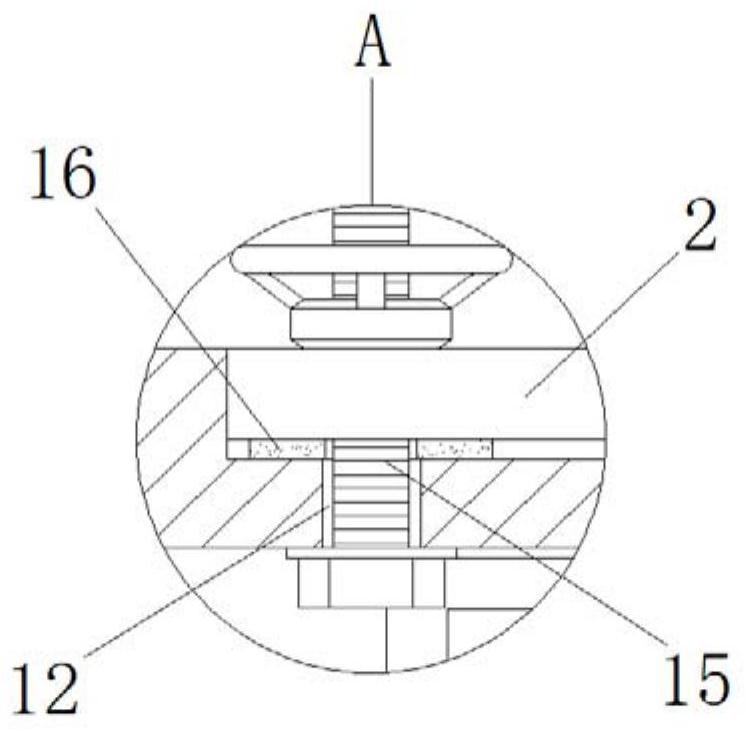
[0029] Embodiment 2: The interior of the adjustment groove 1 is respectively provided with an adjustment limit groove 12, and the two ends of the adjustment limit groove 12 are respectively penetrated with locking bolts 15, and the locking bolts 15 can slide inside the adjustment limit groove 12, The tops of the locking bolts 15 run through one side of the inside of the moving connecting plate 2 respectively, and the outer portions of the locking bolts 15 are respectively sleeved with locking turntables 11, and the insides of the locking turntables 11 are respectively provided with internal threads. Fastening gaskets 16 are respectively provided, and the fastening gaskets 16 are respectively arranged between the top end of the adjustment groove 1 and the bottom end of the moving connecting plate 2;

[0030] Specifically, such as figure 1 , figure 2 , image 3 with Figure 4As shown, and by sliding the locking bolt 15 inside the adjustment limit groove 12 provided inside th...

Embodiment 3

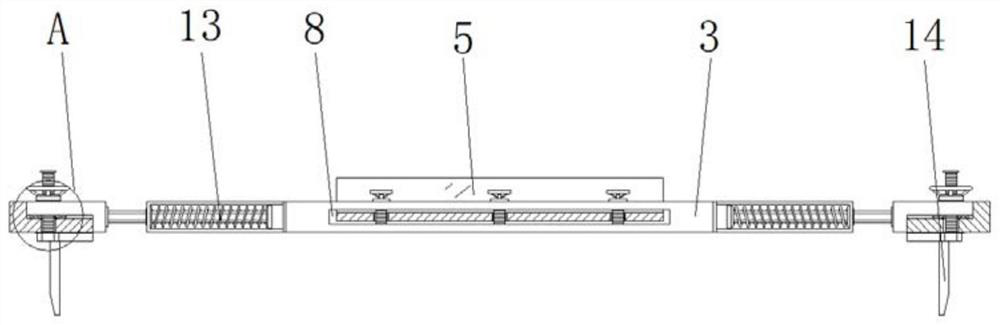
[0031] Embodiment 3: There are four sets of fixed cylinders 6, and the fixed cylinders 6 are respectively symmetrical about the vertical center line of the positioning horizontal plate 3, and one side of the fixed cylinder 6 is respectively inserted with a telescopic rod 7, and one of the telescopic rods 7 The sides are respectively fixedly connected with one side of the mobile connecting plate 2;

[0032] Specifically, such as figure 1 , figure 2 , Figure 4 with Figure 5 As shown, when in use, the purpose of connecting and fixing the moving connecting plate 2 and the positioning horizontal plate 3 is achieved by fixedly connecting the fixed cylinder 6 on both sides of the positioning horizontal plate 3 and the telescopic rods 7 inserted on one side respectively. The length between the positioning horizontal plate 3 and the moving connecting plate 2 can be adjusted by adjusting the length of the telescopic rod 7 plugged into the fixed cylinder 6, so that the width of the...


PUM


Abstract

The invention discloses an embedded steel bar clamping groove positioning device which comprises two sets of positioning transverse plates, and the two sets of positioning transverse plates are the same in size. According to the embedded steel bar clamping groove positioning device, the adjusting grooves are formed in the two sides of the positioning transverse plate correspondingly, when the embedded steel bar clamping groove positioning device is used, the movable connecting plate and the adjusting grooves are connected through locking bolts, the adjusting grooves and the movable connecting plate are matched in an L shape, and the locking bolts are used for adjusting sliding in the limiting grooves; the movable connecting plate can be adjusted to move, after the movable connecting plate is adjusted in place, the locking rotary disc which is connected to the outer top end of the locking bolt in a sleeving mode and internally provided with an internal thread is connected and fixed, the adjusting groove and the movable connecting plate are connected and fastened, the connecting stability is improved through the fastening gasket, and safety accidents caused by loosening in the using process are prevented; therefore, the purpose of quickly adjusting the distance between the positioning transverse plates is achieved, and the problem that the distance between the positioning assemblies cannot be adjusted is solved.

Description

technical field [0001] The invention relates to the technical field of building construction, in particular to a pre-embedded steel bar slot positioning device. Background technique [0002] With the development of society and economy, my country's infrastructure construction has developed rapidly, and the rapid development of infrastructure construction requires the use of a large amount of building materials to meet such rapid infrastructure development. In the existing society, the main body of the building mainly uses steel bars Concrete is an integrally poured structure. Therefore, steel bars are widely used in various building structures as an indispensable building material in the development of infrastructure. Steel bars are used as steel for reinforced concrete and prestressed reinforced concrete. Steel bars mainly bear tensile stress in concrete. Concrete has a greater bonding capacity, so it can better withstand external forces. The cross-section of the steel bar is...

Claims


Application Information

Patent Timeline
Patent Type & Authority Applications(China)
IPC IPC(8): E04C5/16
CPCE04C5/16
Inventor 刘宏伟郭新朋丁健刘功厂
Owner 陕西建工第十四建设有限公司
Why Eureka
Try Eureka