
Debugging method for micro-strip power divider after laser welding and packaging

A microstrip power divider and laser welding technology, which is used in connection devices, waveguide devices, electrical components, etc., can solve the problem of not having a microstrip power divider laser, etc., achieves a simple and easy debugging method, and improves microwave power. The effect of improving performance and debugging work efficiency

Active Publication Date: 2022-03-29
LEIHUA ELECTRONICS TECH RES INST AVIATION IND OF CHINA
View PDF5 Cites 0 Cited by
  • Summary
  • Abstract
  • Description
  • Claims
  • Application Information

AI Technical Summary

Problems solved by technology

At present, there is no debugging method for microstrip power dividers after laser packaging

Method used

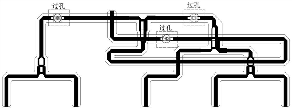
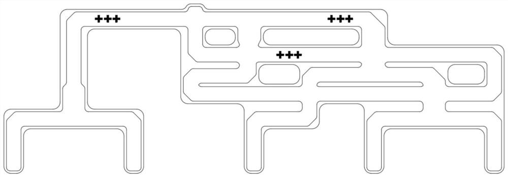
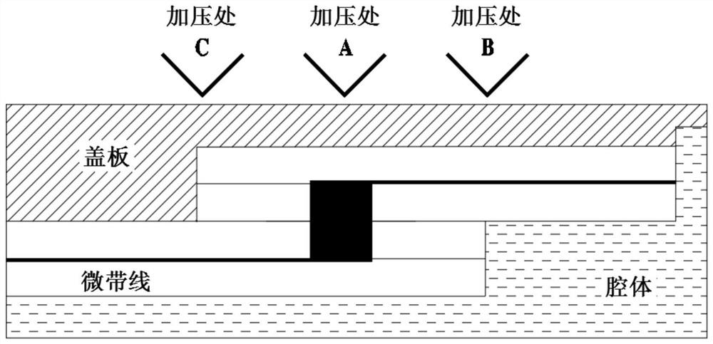

Image

  • Debugging method for micro-strip power divider after laser welding and packaging
  • Debugging method for micro-strip power divider after laser welding and packaging
  • Debugging method for micro-strip power divider after laser welding and packaging

Examples


Embodiment Construction

[0035] Embodiments of the present invention will be described in detail below in conjunction with the accompanying drawings.

[0036] Embodiments of the present invention are described below through specific examples, and those skilled in the art can easily understand other advantages and effects of the present invention from the content disclosed in this specification. Apparently, the described embodiments are only some of the embodiments of the present invention, but not all of them. The present invention can also be implemented or applied through other different specific implementation modes, and various modifications or changes can be made to the details in this specification based on different viewpoints and applications without departing from the spirit of the present invention. It should be noted that, in the case of no conflict, the following embodiments and features in the embodiments can be combined with each other. Based on the embodiments of the present invention,...


PUM

PropertyMeasurementUnit
depthaaaaaaaaaa

Abstract

The invention belongs to the technical field of microwave antennas, and relates to a debugging method for a micro-strip power divider after laser welding packaging. The microstrip power divider comprises a cavity, a cover plate, a microstrip line circuit board and a connector. The cavity and the cover plate are packaged in a laser welding mode. The microstrip line circuit board and the connector are mounted in the cavity; the debugging method of the micro-strip power divider after laser welding packaging comprises the following steps: applying force and / or impact to the outside of the cavity and / or the cover plate to enable the cover plate to generate elastic and / or plastic deformation, and debugging the micro-strip circuit board and / or the connector. The micro-strip power divider subjected to laser packaging can be debugged and repaired, the microwave electrical performance of the micro-strip power divider is guaranteed, and the high and low temperature stability of the micro-strip power divider is guaranteed.

Description

technical field [0001] The invention belongs to the technical field of microwave antennas, and relates to a debugging method for a microstrip power divider after laser welding and packaging. Background technique [0002] The microstrip power divider is an important part of the source phased array radar antenna system, which has a great influence on the performance of the antenna and the overall performance of the radar. There are many models and large quantities, and the tasks in the production and debugging stage are quite heavy. The microstrip power splitter is composed of a cavity, a cover plate, a microstrip line circuit board and a connector installed in the cavity, and the cavity and the cover plate of the power splitter are packaged by laser welding. Although the power divider has been tested and debugged before laser welding, the microwave electrical performance indicators such as standing wave, insertion loss, phase consistency, and mutual isolation of each port ca...

Claims


Application Information

Patent Timeline
Patent Type & Authority Applications(China)
IPC IPC(8): H01P11/00H01P5/12
CPCH01P11/00H01P5/12
Inventor 潘继康孔德武王森
Owner LEIHUA ELECTRONICS TECH RES INST AVIATION IND OF CHINA
Learn More