
Charge pump circuit and phase-locked loop circuit

A charge pump and circuit technology, applied in the direction of electrical components, automatic power control, etc., can solve the unavoidable problems such as I1 and I2 current mismatch

Pending Publication Date: 2022-03-29
合肥大唐存储科技有限公司
View PDF0 Cites 0 Cited by
  • Summary
  • Abstract
  • Description
  • Claims
  • Application Information

AI Technical Summary

Problems solved by technology

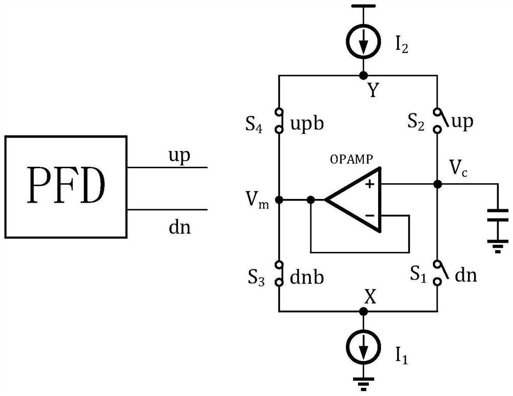
[0004] A charge pump structure widely used in engineering is as follows figure 1 As shown in the figure, when S1 and S2 are disconnected, S3 and S4 are closed, and the operational amplifier (OPAMP) makes the voltages at points X and Y consistent with the Vc voltage through feedback, which avoids the next time S1 and S2 are closed. The parasitic capacitances at points X and Y have a charge sharing effect on the voltage of Vc. Although this structure improves charge sharing, it cannot avoid the current mismatch between I1 and I2.

Method used


Image

  • Charge pump circuit and phase-locked loop circuit
  • Charge pump circuit and phase-locked loop circuit
  • Charge pump circuit and phase-locked loop circuit

Examples


Embodiment Construction

[0087] The application describes a number of embodiments, but the description is illustrative rather than restrictive, and it will be obvious to those of ordinary skill in the art that within the scope of the embodiments described in the application, There are many more embodiments and implementations. Although many possible combinations of features are shown in the drawings and discussed in the detailed description, many other combinations of the disclosed features are possible. Except where expressly limited, any feature or element of any embodiment may be used in combination with, or substituted for, any other feature or element of any other embodiment.

[0088] This application includes and contemplates combinations of features and elements known to those of ordinary skill in the art. The disclosed embodiments, features and elements of this application can also be combined with any conventional features or elements to form unique inventive solutions as defined by the clai...


PUM


Abstract

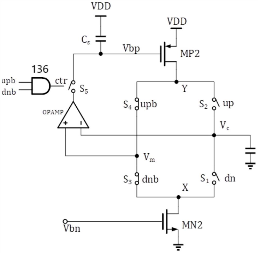
The embodiment of the invention discloses a charge pump circuit and a phase-locked loop circuit. The charge pump circuit comprises a charge and discharge module which enters a charge and discharge state or a sampled state under the control of a PFD; the voltage of the filter capacitor is used for controlling the frequency of the VCO; the sampling control circuit generates a control signal according to a PFD output result to control the operational amplifier to be conducted to perform voltage sampling or stop voltage sampling; after the operational amplifier is conducted, the operational amplifier samples voltage at a plurality of charging and discharging connection ends on a charging and discharging path, generates bias voltage according to the sampled voltage and provides the bias voltage to the charging and discharging module; the voltage sampling and holding module samples the bias voltage of the operational amplifier when the charging and discharging module is in a sampled state, and holds the bias voltage and transmits the bias voltage to the charging and discharging module when the charging and discharging module enters a charging and discharging state. Through the scheme of the embodiment, the problem of current mismatching of a current charge pump circuit is solved.

Description

technical field [0001] The embodiment of the present application relates to the charge pump circuit design technology, especially to a charge pump circuit and a phase-locked loop circuit. Background technique [0002] The phase-locked loop (PLL) is an important module in the digital-analog hybrid circuit, which can track the phase and frequency of the input signal and output a low-jitter clock signal. It has become an indispensable module in special chips such as communication system, digital circuit, hard disk drive circuit and CPU (central processing unit). [0003] Charge pumps are widely used in phase-locked loop circuits. The addition of charge pumps can provide infinite loop gain and capture range for the loop. In the phase-locked loop circuit, the charge pump is used to convert the digital signal output by the phase frequency detector (PFD) into an analog signal, and the analog signal controls the frequency change of the voltage-controlled oscillator (VCO). The perf...

Claims


Application Information

Patent Timeline
Patent Type & Authority Applications(China)
IPC IPC(8): H03L7/085H03L7/089H03L7/093H03L7/18
CPCH03L7/085H03L7/093H03L7/0891H03L7/18
Inventor 郭锐
Owner 合肥大唐存储科技有限公司
Learn More