General image projection equipment imaging definition detection method

A detection method and technology of clarity, applied in image communication, television, electrical components, etc., can solve problems such as insufficient accuracy, low test efficiency, affecting test results, etc., to solve the influence of unfavorable factors, test results are objective and reliable, The effect of improving positioning accuracy

Pending Publication Date: 2022-03-29
成都信和创业科技有限责任公司
View PDF0 Cites 0 Cited by
  • Summary
  • Abstract
  • Description
  • Claims
  • Application Information

AI Technical Summary

Problems solved by technology

Since the vision of each tester is different, it will affect the test results, so the manual test can only give qualitative test results, and the test results will vary with the individual differences of the testers, the accuracy is insufficient, and the test efficiency is low

Method used


Image

  • General image projection equipment imaging definition detection method
  • General image projection equipment imaging definition detection method
  • General image projection equipment imaging definition detection method

Examples


Embodiment 1

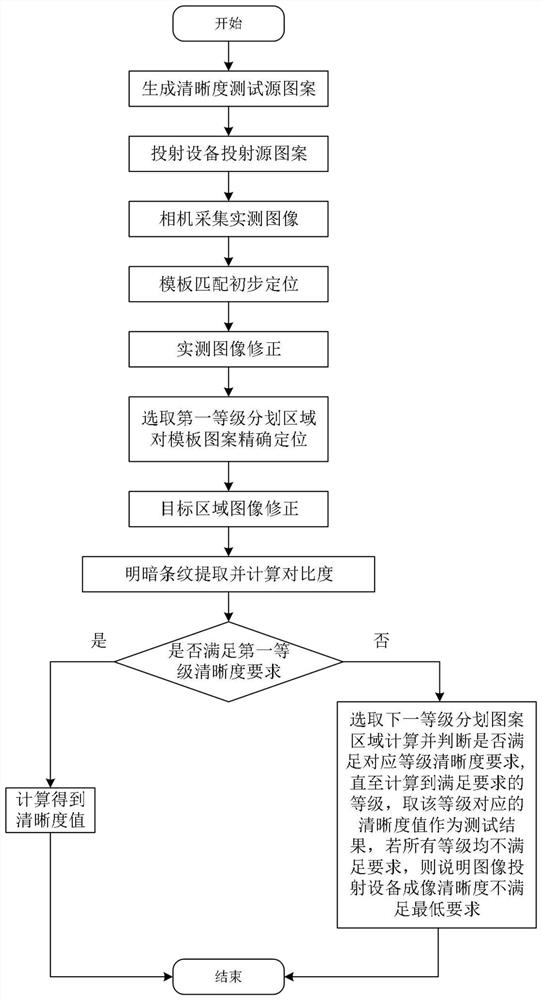
[0036] A general detection method for the detection method of image definition of image projection equipment:

[0037] Step 1: Generate an electronic image file in a standard format according to the definition test source pattern, import it into the AR glasses display drive device, and control the AR glasses to display the definition test source pattern;

[0038] Step 2: Use the calibrated camera to collect the sharpness test source pattern projected by the AR glasses to obtain the measured image;

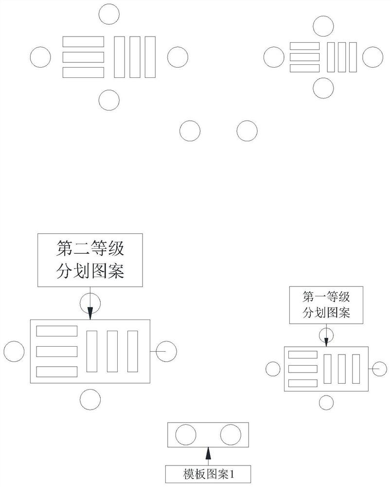
[0039] Step 3: Perform template matching on the collected measured image using the template pattern 1 as a template to obtain the position of the template pattern 1 in the entire measured image;

[0040] Step 4: Select the region of interest of template pattern 11 and template pattern 12 in the measured image, and accurately locate the cross center of the two template patterns, and the center coordinates are respectively Cor11 (u11, v11) and Cor12 (u12, v12);

[0041]Step 5: Calcu...

specific Embodiment approach

[0057] Now take the night vision goggles as the measured object to set forth the second specific embodiment of the present invention: first make the target plate that meets the requirements of the aforementioned sharpness test source pattern form, and according to the specific classification of the night vision goggles, the target plate is made differently;

[0058] If it is a low-light night vision goggle, the pattern in the form of a source pattern is carved in the base plate of the opaque material, and the corresponding bright stripe area is pierced, and a light source that meets the low-light requirements is set behind the target plate and turned on, so that the light can pass through. After passing through the pattern stripe area in the target plate and imaging through the night vision goggles, the measured image is obtained after being photographed by the camera;

[0059] If it is an infrared night vision goggle, the pattern in the form of a source pattern is engraved on ...


PUM


Abstract

The automatic test requirement of the image projection equipment is met, the machine vision technology is adopted for detection, the problem that the current manual test result is inaccurate is avoided, the test result is objective and reliable, the imaging definition index of the image projection equipment can be reflected, and the accuracy of the test result is improved through the combination of preliminary positioning and accurate positioning. The influence of adverse factors appearing in the actual measurement image is solved, and the positioning precision of the target area is improved. The method comprises the following steps: firstly, determining an approximate position of a template area through preliminary positioning, calculating a scaling ratio and a rotation angle, and performing preliminary correction on an actually measured image; transmitting the preliminary positioning result to the vicinity of the target area, accurately positioning the pattern of the enhanced positioning template, determining the scaling and the rotation angle of the target area, correcting the image again, and determining the accurate position of the final target area; the method has universality and can be applied to imaging definition testing of optical equipment such as projectors, AR glasses, helmet displays and night vision goggles for direct or indirect imaging for human eye observation.

Description

technical field [0001] The present invention mainly relates to the technical field of image projection equipment, in particular to a general imaging definition detection method of image projection equipment. Background technique [0002] A projector is an optical device that is often used in daily life and office work. It can project images onto a screen through optical devices, and the human eye can observe the screen to see the enlarged projected image. AR glasses are also a device similar to a projector, which can be understood as a reduced version of a head-mounted projector. The image source pattern is transmitted and enlarged through optical devices, and the image is directly imaged at the entrance pupil of the human eye. The helmet-mounted display is an optical device similar to AR glasses. By organically combining the optical device with the helmet body structure of the helmet, the two-dimensional image source pattern is transmitted and enlarged through the optical d...

Claims


Application Information

Patent Timeline
IPC IPC(8): H04N1/00H04N17/02
CPCH04N1/00037H04N17/02
Inventor 李小强苏伟龚科毕丛林唐洋
Owner 成都信和创业科技有限责任公司
Why Eureka
Try Eureka