Peristaltic pump

A peristaltic pump and pump tube technology, applied in the field of peristaltic pumps, can solve the problems of easy falling off, complex structure, low control precision, etc., and achieve the effect of good compression effect.

Pending Publication Date: 2022-04-01
美高怡生生物电子科技(北京)有限公司
View PDF0 Cites 2 Cited by
  • Summary
  • Abstract
  • Description
  • Claims
  • Application Information

AI Technical Summary

Problems solved by technology

Existing peristaltic pumps are complex in design and structure, and the control accuracy is not high. The pump tube is easy to slide with the pump head when the pump head rotates, and sometimes it is easy to fall off.
The clamping structure of the pump head is relatively weak and easy to break
Therefore, a peristaltic pump is designed to solve the problems that the pump tube of the existing peristaltic pump is easy to slide off and the compression structure is weak

Method used


Image

  • Peristaltic pump
  • Peristaltic pump
  • Peristaltic pump

Examples


Embodiment 1

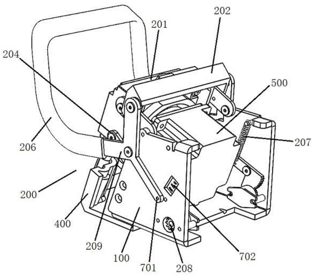
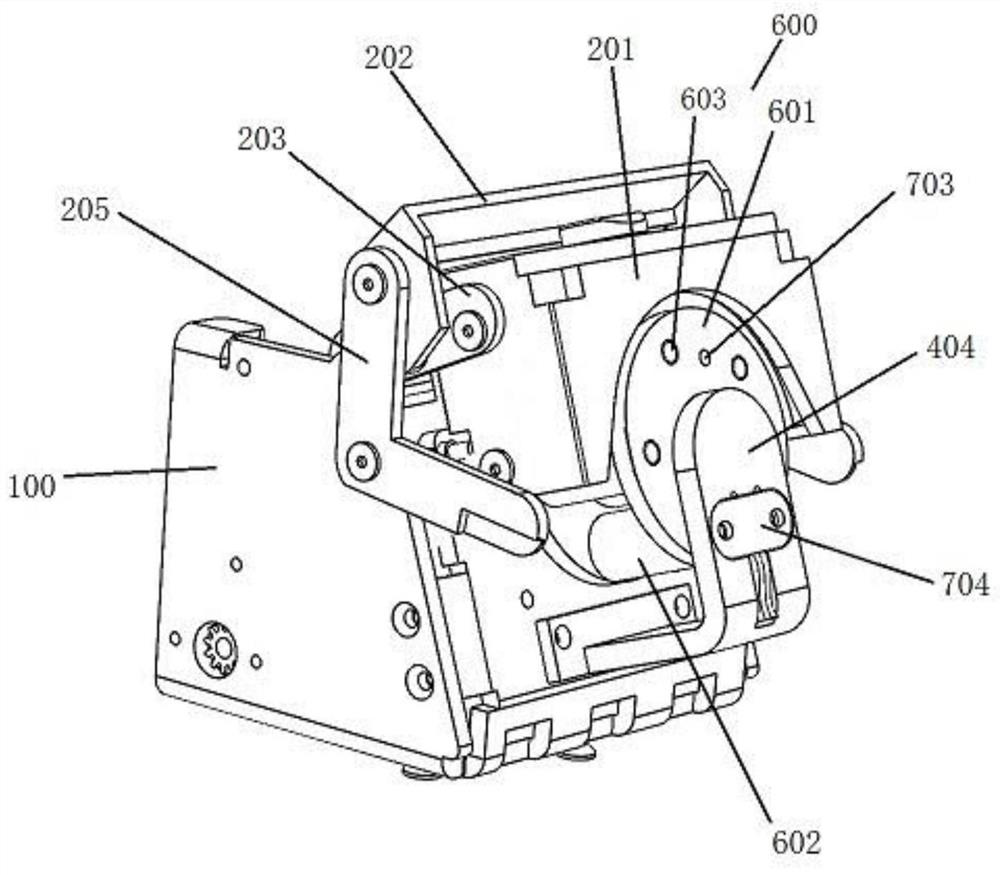
[0030] see Figure 1 to Figure 4 , the present invention provides a peristaltic pump, including a frame 100 , a rocker assembly 200 , a pressing block 300 , a pump tube fixing assembly 400 , a driving motor 500 and a roller assembly 600 . The drive motor 500 is installed in the frame 100, the output shaft of the drive motor 500 is fitted with a roller assembly 600, and the pump tube 101 is placed on the roller assembly 600, and the roller assembly 600 is used to drive the pump tube 101 to peristalticly supply liquid under the drive of the drive motor 500. The pump tube fixing assembly 400 is fixedly connected to the frame 100, the rocker assembly 200 is rotatably arranged on the frame 100, the pressing block 300 is arranged on the rocker assembly 200, the pressing block 300 is located above the roller assembly 600, and the rocker assembly 200 can drive the pressing block 300 close to the roller assembly 600 to cooperate with the roller assembly 600 to press the pump tube 101 o...

Embodiment 2

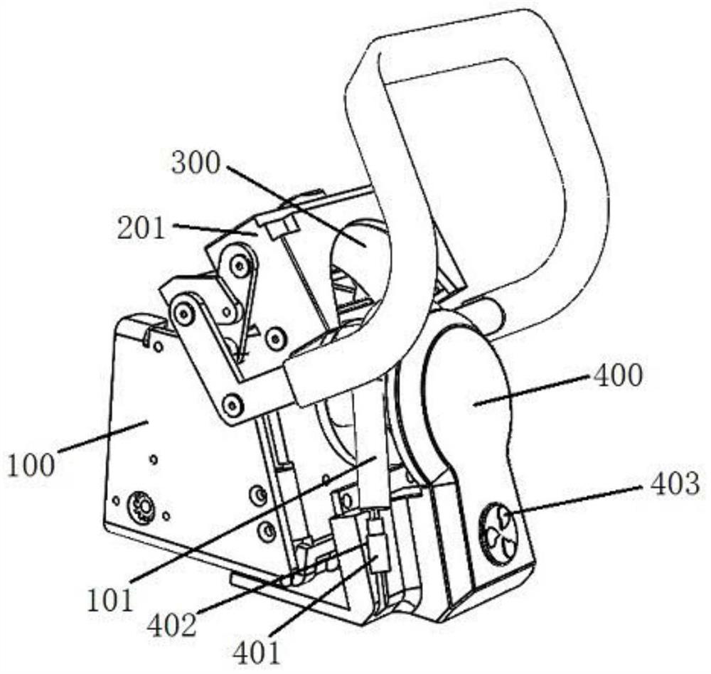
[0047] see image 3 , this embodiment provides a peristaltic pump. This embodiment is an improvement made on the technical basis of the first embodiment above. The difference between this embodiment and the first embodiment is that an indicator light 403 is installed on the lower part of the pump tube fixing assembly 400, and the flashing frequency of the indicator light 403 is controlled by the microcontroller. control, the flickering frequency of the indicator light 403 is related to the liquid supply rate of the pump tube 101 .

[0048] In this embodiment, three indicator lights 403 are evenly embedded in the outer surface of the lower part of the pump tube fixing assembly 400 along the ring, and the indicator lights 403 are electrically connected to the microcontroller. Adjust the flashing frequency of the indicator light 403 to be consistent or proportional to the liquid supply rate of the pump tube 101 through the rotation of the roller assembly 600, that is, the faster...


PUM


Abstract

The invention provides a peristaltic pump which comprises a rack, a rocker assembly, a pressing block, a pump pipe fixing assembly, a driving motor and a roller assembly, the driving motor is installed in the rack, an output shaft of the driving motor is sleeved with the roller assembly, a pump pipe is placed on the roller assembly, and the rocker assembly is connected with the roller assembly. The roller assembly is used for pushing the pump pipe to creep for liquid supply under the driving of the driving motor, the pump pipe fixing assembly is fixedly connected to the rack and used for fixing the two ends of the pump pipe, the rocker assembly is rotationally arranged on the rack, the pressing block is arranged on the rocker assembly, and the pump pipe fixing assembly is used for fixing the two ends of the pump pipe. And the rocker assembly can drive the pressing block to be close to the rolling wheel assembly so as to be matched with the rolling wheel assembly to press the pump pipe on the rolling wheel assembly. The two ends of the pump pipe are fixed through the pump pipe fixing assembly, it is guaranteed that the pump pipe is not prone to moving and falling off, and the pressing block is tightly attached to the pump pipe to prevent liquid in the pump pipe from flowing back.

Description

technical field [0001] The invention relates to the field of pump body equipment, in particular to a peristaltic pump. Background technique [0002] A peristaltic pump is a pump body that conveys fluid by alternately squeezing and releasing an elastic conveying hose. It is used in many fields of production and life. The existing peristaltic pump has a complex design and structure, and the control accuracy is not high. The pump tube is easy to slide with the pump head when the pump head is rotating, and sometimes it is easy to fall off. The clamping structure of the pump head is relatively weak and easily damaged. Therefore, a peristaltic pump is designed to solve the problems that the pump tube of the existing peristaltic pump is easy to slide off and the compression structure is weak. Contents of the invention [0003] In order to overcome the deficiencies in the prior art, the present application provides a peristaltic pump. [0004] In order to achieve the above purp...

Claims


Application Information

Patent Timeline
Patent Type & Authority Applications(China)
IPC IPC(8): F04B43/12F04B17/03F04B53/00F04B49/10
Inventor 任宏超陈堃
Owner 美高怡生生物电子科技(北京)有限公司
Why Eureka
Try Eureka