Vertical bearing mounting device for motor rotor

A technology of motor rotor and bearing device, which is applied in the direction of electromechanical device, manufacture of motor generator, manufacture of stator/rotor body, etc. It can solve the problems of inconvenient automatic conveying of raw materials and low production efficiency

Active Publication Date: 2022-04-01
QUANNAN CHAOYA TECH
View PDF11 Cites 0 Cited by
  • Summary
  • Abstract
  • Description
  • Claims
  • Application Information

AI Technical Summary

Problems solved by technology

[0006] The purpose of the present invention is to provide a vertically mounted bearing device for motor rotors, which is mainly used to solve the problems that the horizontally mounted bearings of electronic rotors are inconvenient to automatically transport raw materials and the production efficiency is not high

Method used


Image

  • Vertical bearing mounting device for motor rotor
  • Vertical bearing mounting device for motor rotor
  • Vertical bearing mounting device for motor rotor

Examples


Embodiment 1

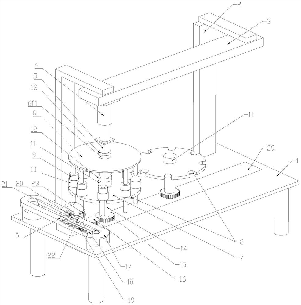
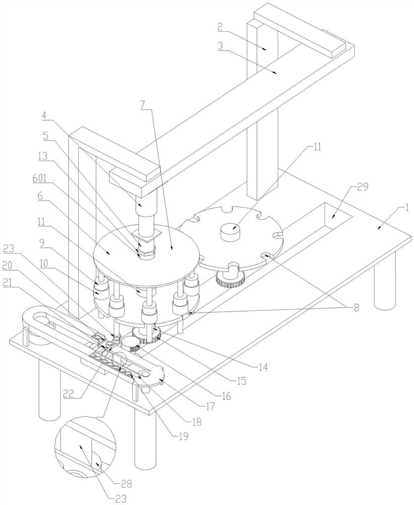
[0029] A kind of motor rotor vertical mounting bearing device of this embodiment, such as Figure 1-7 As shown, it includes a workbench 1, the inner side of the workbench 1 is fixedly connected with a column 2, the top of the column 2 is fixedly connected with a slide rail 3, and the bottom of the slide rail 3 is slidably connected with a cylinder I4. The bottom of the cylinder Ⅰ4 is connected with a connecting rod 5, through which a circular supporting plate 7 is suspended and connected, the middle of the top of the supporting plate 7 is connected with a rotating drum 11, and the bottom of the connecting rod 5 is fixedly connected with an electromagnet 12, through the electromagnetic Iron 12 absorbs and connects supporting plate 7. Supporting plate 7 is provided with multiple sets of placement grooves 8, and rotor 9 is vertically placed through placing grooves 8, and the middle of rotor 9 is connected with rotating shaft, and the bottom of supporting plate 7 is fixed with rot...


PUM


Abstract

The invention relates to the technical field of motor installation, and provides a vertical bearing installation device for a motor rotor. Comprising a working table, the working table is fixedly connected with a sliding rail through a stand column, the sliding rail is slidably connected with an air cylinder I, the bottom of the air cylinder I is connected with a connecting rod, a tray is connected through the connecting rod in a hanging mode, rotors are vertically placed through a containing groove, and the tray is driven by a motor to rotate; a conveying belt is fixedly supported on one side of the workbench, a bearing is conveyed on the conveying belt, an air cylinder II is fixedly supported on the workbench, a push cylinder is connected to the top end of the air cylinder II, the bearing is installed on a rotating shaft of a rotor through the push cylinder, a rear baffle is fixed to the workbench through a support, and the support is connected with a front baffle and a push rod through an air cylinder. A to-be-mounted bearing is pushed to the top end of the push cylinder through the push rod. The automatic feeding device has the beneficial effects that the rotors and the bearings can be automatically fed, the installation automation degree is improved, and the production efficiency is improved.

Description

technical field [0001] The invention relates to the technical field of motor installation, in particular to a vertically mounted bearing device for a motor rotor. Background technique [0002] The motor bearing installation structure is the key to the long-term and stable operation of the motor. The motor bearing is a connecting piece connecting the motor shaft and the end cover. There are mainly two installation methods for the existing motor bearing. One is to insert the bearing into the bearing chamber of the end cover first, and then insert the rotating shaft; the other is to install the bearings at both ends of the rotating shaft first, and then install the rotor with the bearing installed into the casing. [0003] The first method has lower requirements on the press-fitting machine, but it is easy to cause certain deformation to the end cover or casing, which has some influence on the installation accuracy of the motor. And after the bearing is installed into the end...

Claims


Application Information

Patent Timeline
Patent Type & Authority Applications(China)
IPC IPC(8): H02K15/02H02K15/00
Inventor 张舜黄绪海
Owner QUANNAN CHAOYA TECH
Why Eureka
Try Eureka