Check patentability & draft patents in minutes with Patsnap Eureka AI!

Rotor bearing block, and wind turbine comprising rotor bearing block

A technology for wind turbines and bearing housings, applied in wind engines, engines, wind power generation, etc., can solve problems such as hindering wind turbines, achieve investment cost and service life cost advantages, ensure replacement, and compact design.

Pending Publication Date: 2022-04-01
艾罗迪能源系统有限公司
View PDF6 Cites 0 Cited by
  • Summary
  • Abstract
  • Description
  • Claims
  • Application Information

AI Technical Summary

Problems solved by technology

The disadvantage of this design is the design-related outlay space configuration, which prevents the formation of compact wind turbines

Method used


Image

  • Rotor bearing block, and wind turbine comprising rotor bearing block
  • Rotor bearing block, and wind turbine comprising rotor bearing block

Examples


Embodiment Construction

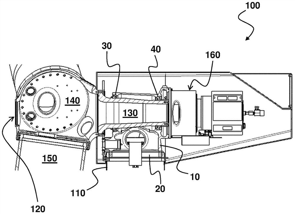
[0041] figure 1 A schematic sectional view of a wind turbine in the nacelle region is shown, which is particularly preferably configured according to the invention as a leeward rotor.

[0042] A particularly preferably constructed wind turbine 100 has a tower 110; a rotor bearing housing 10 constructed according to the invention arranged on the tower 110; a rotor 120 with a rotor shaft 130 mounted in the rotor bearing housing 10; rotor hub 140 flanged to rotor shaft 130 ; and a plurality of rotor blades 150 coupled to rotor hub 140 ; ​​and a generator received by generator base 160 and coupled to rotor shaft 130 .

[0043] It can be clearly seen that the rotor bearing housing 10 is designed with a circular tower connection 20 which forms the upper bearing unit of the azimuth system. The rotor bearing housing 10 also accommodates two ring bearings 30 , 40 which are spaced apart from each other and are designed as tapered roller bearings. As shown in the cross-sectional view, ...


PUM


Abstract

The invention relates to a rotor bearing block (10) for receiving a rotor (120) of a wind turbine (100), comprising a circular tower connection (20) and a rotor bearing having two ring bearings (30, 40) spaced apart from one another for mounting a rotor shaft (130), the ring bearings (30, 40) being designed as tapered roller bearings and being arranged in the tower connection (20) when viewed from above, wherein, when viewed from above, the effective bearing centers of the annular bearings (30, 40) are arranged outside the tower connection (20).

Description

technical field [0001] The invention relates to a rotor bearing housing for receiving a rotor of a wind turbine with a circular tower connection and a rotor bearing having two annular bearings spaced apart from each other for receiving the rotor. The invention also relates to a wind turbine having: a tower; a rotor bearing housing arranged on said tower; a rotor mounted in said rotor bearing housing, said rotor having a rotor shaft; a rotor flange connected to the rotor hub; and at least one rotor blade connected to the rotor hub; and a generator connected to the rotor. Background technique [0002] The global increase in demand for renewable energy, especially wind energy, coupled with the rapid decline in suitable wind turbine sites with sufficient wind speeds, is driving the development of ever larger and more powerful wind turbines. Increases in turbine performance have led to ever greater masses and sizes of components being transported and built, posing significant lo...

Claims


Application Information

Patent Timeline
Patent Type & Authority Applications(China)
IPC IPC(8): F03D80/70
CPCF03D80/70F05B2240/50F05B2240/52F05B2240/54F05B2250/36Y02E10/72F05B2260/90
Inventor M·里斯
Owner 艾罗迪能源系统有限公司
Features
  • R&D
  • Intellectual Property
  • Life Sciences
  • Materials
  • Tech Scout
  • Unparalleled Data Quality
  • Higher Quality Content
  • 60% Fewer Hallucinations
Learn More