
Eureka
For R&D, Eureka makes reading and utilizing patents & technical documents easy.
Eureka AIR
Designed for self-driven R&D workflows. Generate viable solutions, solve complex R&D challenges, empower your innovation with AI.

Eureka Materials
Designed for material experts only. Revolutionize your material R&D, from search, analyze, to developing new materials.

TechResearch
Generate reliable direction feasibility study reports for your R&D in just a few steps.

TechSeek
Discover and master advanced knowledge NOW. Basics, ideas, possibilities, all at once.

TechMind
As an expert in R&D Theories, TechMind can generates customized viable solutions instantly.

TechRisk
Analyze your overall solution with one click, know your potential R&D risks in advance.

TechMonitor
Get weekly tech updates, stay abreast of the latest tech innovations and key insights.
Pin mounting method and pin mounting device for puller
A technology for sliders and pin shafts, which is applied in the field of slider mounting methods and pin mounting devices, which can solve the problems of falling, easy movement of caps, and difficulty in installing copper pins, so as to prevent displacement or falling , Reduce the difficulty of mounting and pinning, and the effect of simple installation process
- Summary
- Abstract
- Description
- Claims
- Application Information
AI Technical Summary
Problems solved by technology
Method used
Image

Examples
Embodiment 1
[0046] see Figure 3 to Figure 14 Shown, a kind of slider pinning method of the present invention comprises the following steps:
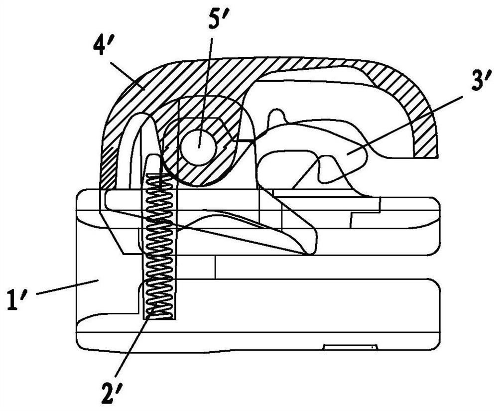
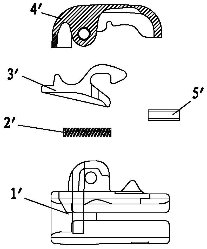
[0047]Step 1. Install the cap 11 to the corresponding position on the slider body 1, and press the cap 11 tightly on the slider body 1, so that the positions of the cap 11 and the slider body 1 remain fixed, so that the slider body 1 and the respective pin installation holes 111 on the cap 11 are connected to form a channel; of course, before this step 1, the spring and the horse hook need to be installed on the slider body 1 first, and the spring and the horse hook are compatible with the existing The installation method is the same, and will not be described in detail here;
[0048] Step 2: Pre-insert the pre-insert 2 into the above channel from one side, after the pre-insert 2 is inserted in place, release the cap 11; because at this time the pre-insert 2 has been inserted into the pin on the slider body 1 and the cap 11 In the shaft installat...
Embodiment 2
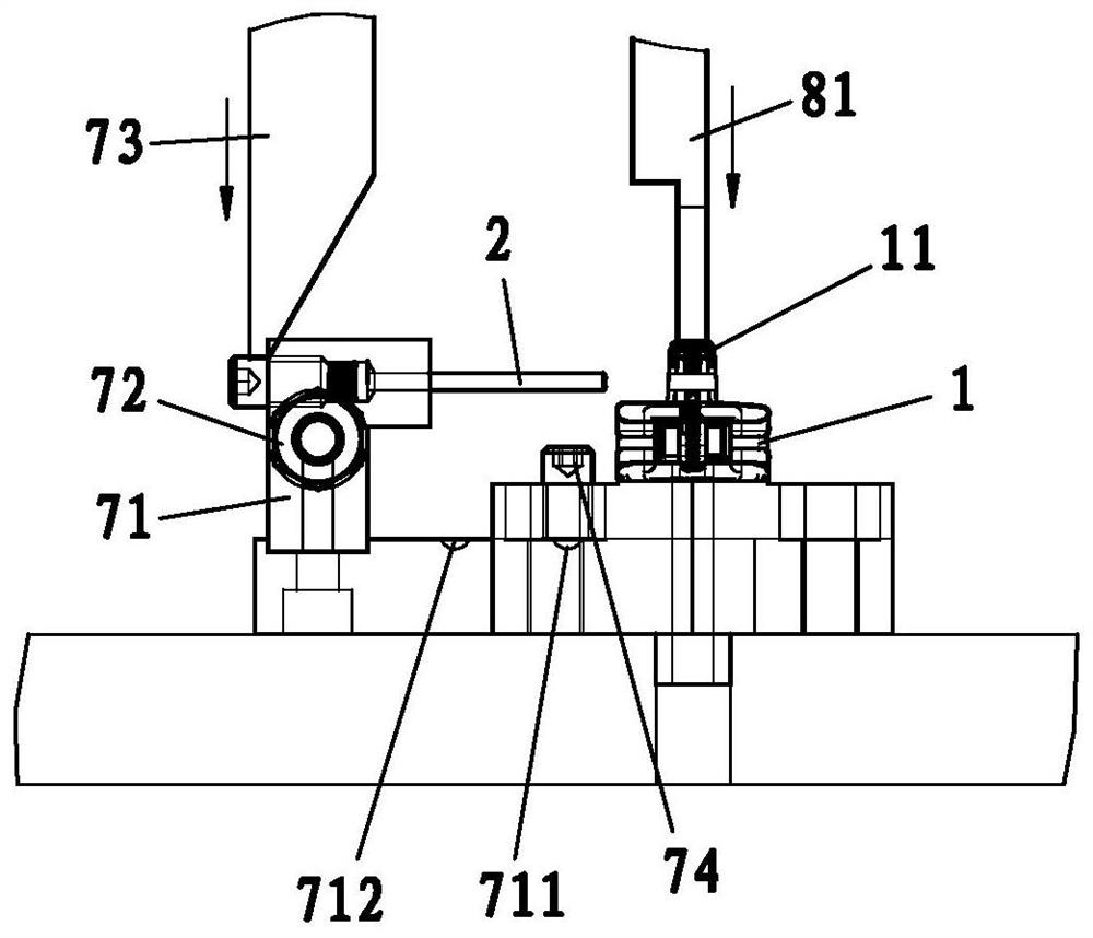
[0060] see Figure 3 to Figure 14 As shown, a pin loading device of the present invention includes an assembly machine body 5, a cap conveying mechanism 5a and a pin shaft conveying mechanism 6;
[0061] The assembly machine body 5 includes a rotating bottom plate 51 and an upper plate 52 that is located above the rotating bottom plate 51 and can be lifted up and down; the assembly machine body 5 is provided with a cap installation station and pins around the rotating bottom plate 51. A shaft installation station, so that the slider body 1 and the cap 11 can be transported to the desired station by rotating the lower plate 51;
[0062] The rotary lower plate 51 is provided with a slider body carrier 53, the slider body 1 is loaded on the slider body carrier 53, and one side of the slider body carrier 53 is provided with a To the pre-insertion mechanism 7 on the slider body 1 and the cap 11; the cap conveying mechanism 5a is arranged on the cap installation station to realize ...
PUM
 Abstract
Description
Claims
Application Information
 - R&D Engineer
- R&D Manager
- IP Professional
- Industry Leading Data Capabilities
- Powerful AI technology
- Patent DNA Extraction
Browse by: Latest US Patents, China's latest patents, Technical Efficacy Thesaurus, Application Domain, Technology Topic, Popular Technical Reports.
© 2024 PatSnap. All rights reserved.Legal|Privacy policy|Modern Slavery Act Transparency Statement|Sitemap|About US| Contact US: help@patsnap.com