Mirror symmetry concave-convex wing type fin type PCHE flow channel

A mirror-symmetrical, fin-type technology, which is applied in the field of discontinuous airfoil fin flow channel and concave-convex airfoil fin type PCHE flow channel, can solve the problems of poor heat transfer performance and achieve improved heat transfer capacity and high heat transfer efficiency. Efficiency improvement, eddy current and backflow reduction effect

Pending Publication Date: 2022-04-05
BEIHANG UNIV
View PDF5 Cites 0 Cited by
  • Summary
  • Abstract
  • Description
  • Claims
  • Application Information

AI Technical Summary

Problems solved by technology

[0005] In order to overcome the above-mentioned shortcomings of poor heat transfer performance of the traditional airfoil finned flow channel, the purpose of the present invention is to propose a mirror-symmetric concave-convex airfoil finned PCHE flow channel, which can be r

Method used


Image

  • Mirror symmetry concave-convex wing type fin type PCHE flow channel
  • Mirror symmetry concave-convex wing type fin type PCHE flow channel
  • Mirror symmetry concave-convex wing type fin type PCHE flow channel

Examples


Example Embodiment

[0024] Next, the technical solution in the embodiment of the present invention will be described, and the technical solutions in the embodiments of the present invention need to be pointed out that the embodiments described below are all exemplary part embodiments, not all embodiments, intended to clearly illustrate The technical characteristics and advantages of the present invention.
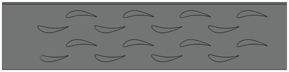
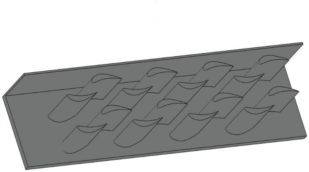
[0025] Attachment in the embodiment of the present invention figure 1 In the description, it is to be understood that the term "lateral" refers to the axial X direction, "longitudinal" refers to the spacing of the leading edge of the unit body 1 and the leading edge of the unit body 3 in the coordinate axis X direction. The "longitudinal interval" refers to the spacing of the leading edge of the unit body 1 and the leading edge of the unit body 2 in the coordinate axis z direction, and "interleaved distance" refers to the spacing of the leading edge of the unit body 1 and the leading edge of the u...


PUM

PropertyMeasurementUnit
Widthaaaaaaaaaa
Vertical spacingaaaaaaaaaa
Horizontal spacingaaaaaaaaaa

Abstract

The invention discloses a mirror symmetry concave-convex wing type fin type PCHE flow channel. The core lies in design and arrangement of concave-convex wing type fin unit bodies. The efficient heat exchange runner is suitable for heat exchange of gaseous fluid or supercritical fluid, and a PCHE heat exchange core is formed by stacking a plurality of runners. And the heat exchange capacity is obviously improved on the premise of low pressure loss. The PCHE flow channel structurally comprises a concave-convex wing type fin unit body, a heat exchange plate and a frame. The profile parameter design of the wing-shaped fins refers to the concave-convex wing-shaped molded line design, adjacent rows are in mirror symmetry, a plurality of rows of runners are copied and formed at certain intervals in the transverse direction and the longitudinal direction, the runners are arranged on a heat exchange plate, inlet and outlet spaces are reserved, and PCHE single-layer runners are obtained. Compared with a traditional Z-shaped flow channel and a traditional wing-shaped fin type flow channel, vortex is weakened and friction is reduced through streamline design in the design process, and heat exchange is enhanced by destroying a boundary layer and increasing turbulent flow. Compared with a traditional airfoil profile design, the airfoil profile has the characteristics that the pressure loss increment is small, the weight is light, and the comprehensive heat exchange performance is remarkably improved.

Description

technical field [0001] The invention belongs to the technical field of high-efficiency compact heat exchanger PCHE, and relates to a discontinuous airfoil-shaped fin flow passage suitable for the circulation of supercritical fluid and general fluid in the PCHE, in particular to a mirror-symmetric concave-convex airfoil-fin flow channel PCHE runner. Background technique [0002] Heat exchangers are important components for energy recovery in modern industry. Heat exchanger optimization by compacting dimensions and increasing the heat transfer area is the key to reducing industrial costs. The printed circuit heat exchanger (PCHE), which has developed rapidly in recent years, is considered to be the first choice for efficient heat transfer under high pressure and confined space due to its compactness, high efficiency, safety and reliability. It is used in liquefied natural gas, aerospace, chemical processing, nuclear power and solar energy There are a wide range of applicatio...

Claims


Application Information

Patent Timeline
IPC IPC(8): F28D9/00F28F3/04
Inventor 付衍琛徐国强祁含闻洁全永凯
Owner BEIHANG UNIV
Why Eureka
Try Eureka