Method for designing low-Mach-number flight total enthalpy platform based on existing hypersonic wind tunnel

A hypersonic and Mach number technology, applied in aircraft component testing, machine/structural component testing, instruments, etc., can solve problems such as inability to simulate local conditions, achieve rapid formation of test capabilities, improve test capability systems, and reduce investment cost effect

Active Publication Date: 2022-04-05
中国空气动力研究与发展中心超高速空气动力研究所
View PDF8 Cites 4 Cited by
  • Summary
  • Abstract
  • Description
  • Claims
  • Application Information

AI Technical Summary

Problems solved by technology

Existing conventional hypersonic wind tunnels have formed large, medium and small supporting test capability systems with reasonable dimensions, which are necessary for simulating aircraft flight Mach number, local pressure, flight angle, etc., but cannot simulate local conditions under real flight conditions. Zong Han

Method used


Image

  • Method for designing low-Mach-number flight total enthalpy platform based on existing hypersonic wind tunnel
  • Method for designing low-Mach-number flight total enthalpy platform based on existing hypersonic wind tunnel
  • Method for designing low-Mach-number flight total enthalpy platform based on existing hypersonic wind tunnel

Examples


Embodiment 1

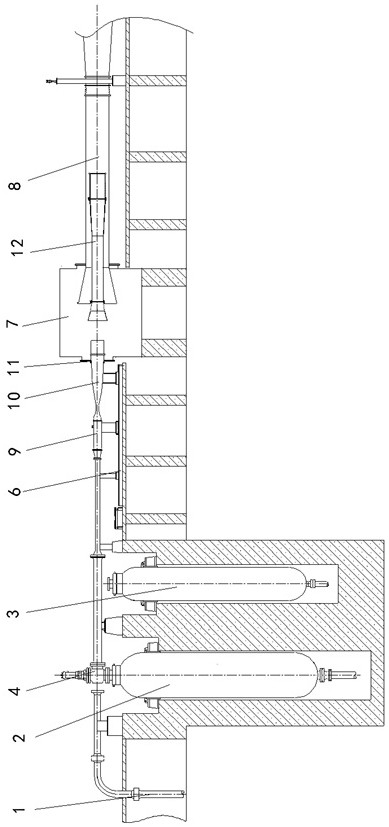
[0082] This embodiment is a wind tunnel test platform for reproducing the total flight enthalpy of Mach number 2-3.

[0083] Such as figure 2 As shown, in this embodiment, the Mach number 8 heater 2 in the existing wind tunnel is selected to establish a wind tunnel test platform for reproducing the total flight enthalpy of Mach number 2-3. On the existing wind tunnel equipment supporting device 6, the existing wind tunnel high-pressure air source system 1, the existing wind tunnel Mach number 8 thermal valve 4, the Mach number 2-3 stable section and transition section 9, and the Mach number 2-3 are sequentially connected. 3 The nozzle 10, the connecting section 11 between the new nozzle with Mach number 2-3 and the original test section, the existing wind tunnel test section 7 and the existing wind tunnel diffuser 8, and in the existing wind tunnel diffuser 8 A platform diffuser 12 is installed in the cavity suit.

Embodiment 2

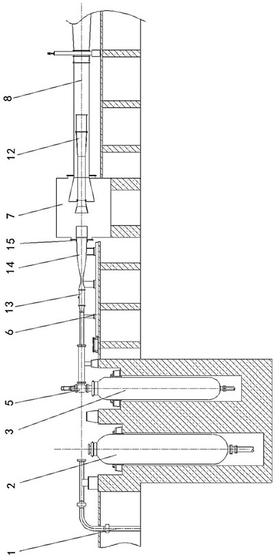
[0085] This embodiment is a wind tunnel test platform for reproducing the total flight enthalpy of Mach number 3.5-4.

[0086] Such as image 3 As shown, in this embodiment, the existing wind tunnel Mach 10 heater 3 is selected to establish a wind tunnel test platform for reproducing the total flight enthalpy of Mach 2-3. On the existing wind tunnel equipment supporting device 6, the existing wind tunnel high-pressure air source system 1, the existing wind tunnel Mach number 10 thermal valve 5, the Mach number 3.5-4 stable section and the transition section 13, and the Mach number 3.5-4 are sequentially connected. 4 The nozzle 14, the connection section 15 between the new nozzle with Mach number 3.5-4 and the original test section, the existing wind tunnel test section 7 and the existing wind tunnel diffuser 8, and in the existing wind tunnel diffuser 8 A platform diffuser 12 is installed in the cavity suit.


PUM


Abstract

The invention belongs to the field of hypersonic wind tunnel test equipment, and discloses a method for designing a low-Mach-number flight total enthalpy platform based on an existing hypersonic wind tunnel. According to the method, existing hypersonic wind tunnels with different calibers are utilized, corresponding jet pipes, stable sections, transition sections and diffusers are matched, a flight total enthalpy wind tunnel test platform with different calibers for reproducing the aircraft in the low Mach number range of 2-4 is built, the simulation total temperature range is 390-950 K, the simulation height is 15-30 kilometers, the effective operation time of the test platform is larger than or equal to 30 seconds, and the test efficiency is greatly improved. Basic theory and test technology research can be carried out on an engine combination power performance test, an aircraft internal and external flow integrated force and heat coupling test, an aircraft aerodynamic thermal load test and the like of an aircraft under a low Mach number, special tests and verification are carried out, and test data and test verification support are provided for aircraft development.

Description

technical field [0001] The invention belongs to the field of hypersonic wind tunnel test equipment, and in particular relates to a method for designing a low Mach number flight total enthalpy platform based on an existing hypersonic wind tunnel. Background technique [0002] In the early days, the wind tunnel test of supersonic aircraft mainly measured the aerodynamic characteristics (aerodynamic force, flight attitude, aerodynamic shape, etc.) or performance of the aircraft. In a supersonic or hypersonic wind tunnel, the airflow expands violently through the nozzle, causing the static temperature of the airflow to drop rapidly. For example, when M≥5, when the temperature of the airflow in the stable section of the wind tunnel is 288K, the temperature of the airflow in the test section of the wind tunnel drops to 48K. At such a low temperature, the air itself condenses, and the condensation heat is released as the condensation proceeds. , and passed to the airflow, so that ...

Claims


Application Information

Patent Timeline
Patent Type & Authority Applications(China)
IPC IPC(8): G01M9/00G01M9/04B64F5/60
CPCY02T90/00
Inventor 孙启志范孝华许晓斌将万秋凌岗巣根明陈映东
Owner 中国空气动力研究与发展中心超高速空气动力研究所
Why Eureka
Try Eureka