Partial polarization signal multi-parameter estimation method based on non-co-located non-uniform polarization array

A polarized signal and non-uniform technology, which is applied in direction finders using radio waves, radio wave direction/deviation determination systems, etc., can solve problems such as ambiguity of incoming wave direction, reduction of array aperture, and increase of mutual coupling. To achieve the effect of saving resources

Pending Publication Date: 2022-04-05
HANGZHOU DIANZI UNIV
View PDF0 Cites 2 Cited by
  • Summary
  • Abstract
  • Description
  • Claims
  • Application Information

AI Technical Summary

Problems solved by technology
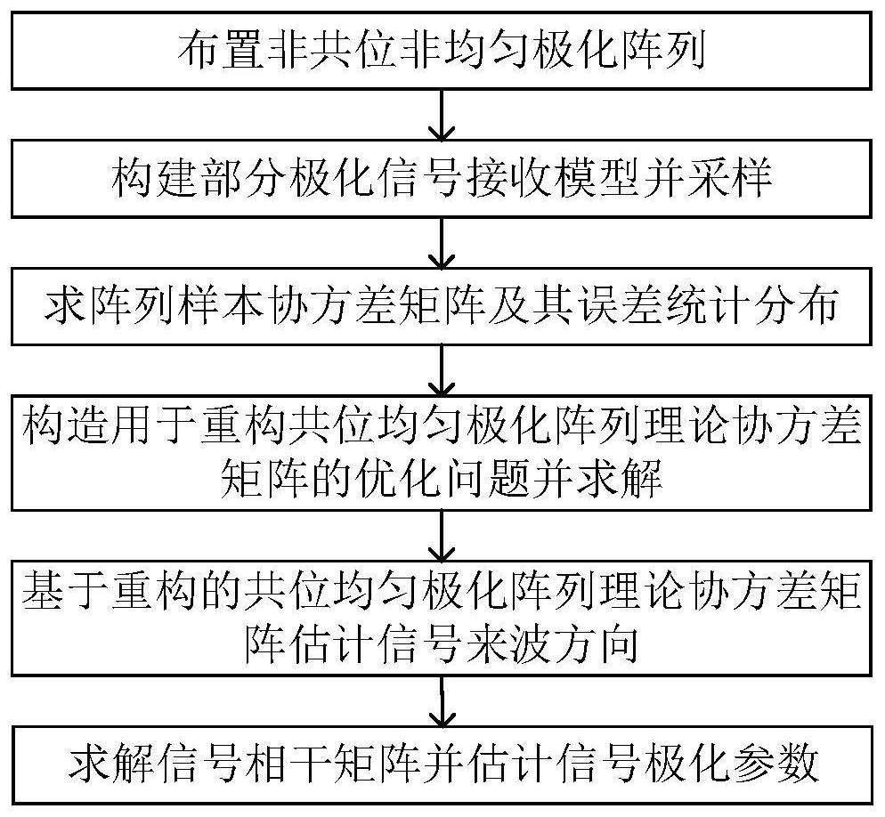
However, due to the uniform structure of the array, in order to avoid the ambiguity of the incoming wave direction, the distance between different polarized elements needs to be no more than a quarter wavelength, which will red

Method used


Image

  • Partial polarization signal multi-parameter estimation method based on non-co-located non-uniform polarization array
  • Partial polarization signal multi-parameter estimation method based on non-co-located non-uniform polarization array
  • Partial polarization signal multi-parameter estimation method based on non-co-located non-uniform polarization array

Examples


Example Embodiment

[0098] Simulation Example 2: Verify that the method of the present invention with the estimation accuracy of the polarization degree with the signal to noise ratio, the number of snapshot is fixed in 200, the signal-to-noise ratio is set to -10 dB to 20dB, and other simulation conditions are the same as the last experiment. . From Image 6 We can see that the root mean square error of the polarization decreases as the signal-to-noise ratio is increased, with higher estimation accuracy. The following table shows the method of the method of the present invention in the signal to noise ratio of 10 dB, and the remaining simulation conditions are the same as the above experiment, and the estimated table of polarization parameters is as follows:

[0099]


PUM


Abstract

The invention discloses a partially polarized signal multi-parameter estimation method based on a non-co-located non-uniform polarized array. The method comprises the following steps of: arranging a non-co-located non-uniform polarization array; constructing a partially polarized signal receiving model and sampling; solving an array sample covariance matrix and error statistical distribution of the array sample covariance matrix; constructing an optimization problem used for reconstructing a co-located uniform polarization array theoretical covariance matrix and solving the optimization problem; estimating a signal incoming wave direction based on a reconstructed co-located uniform polarization array theory covariance matrix; and solving a signal coherence matrix and estimating a signal polarization parameter. According to the method, the array adopts a non-co-location mode, and the phase centers of the polarization units are not overlapped, so that on one hand, the problem of mutual coupling between co-location array polarization units is avoided; and on the other hand, each array element only has one radio frequency channel, so that resources are saved. Then, the array adopts a non-uniform mode, so that the limitation of a uniform array on the aperture of the array is eliminated, and the estimation of the direction of arrival is ensured not to be fuzzy;

Description

technical field [0001] The invention belongs to the technical field of array signal processing, and in particular relates to multi-parameter estimation of partial polarization signals, in particular to a multi-parameter estimation method of partial polarization signals based on non-colocated non-uniform polarization arrays. Background technique [0002] Array antenna technology is used to estimate signal direction of arrival and other parameters, and is widely used in radar, communication and other technical fields. Previous studies mostly assumed that the array is a scalar array, that is, the polarization of the array is single. In this case, when the signal polarization differs from the array polarization, a polarization mismatch will result, reducing the signal-to-noise ratio. To solve this problem, polarimetric arrays (full name polarimetric sensitive arrays) are proposed. The polarized array contains elements of different polarizations, which can receive different pol...

Claims


Application Information

Patent Timeline
IPC IPC(8): G01S3/14
Inventor 潘玉剑崔世豪
Owner HANGZHOU DIANZI UNIV
Why Eureka
Try Eureka