
Stent type UBE operation channel establishing instrument

A surgical channel and channel establishment technology, applied in the field of UBE surgical channel establishment instruments, can solve the problems of inability to establish intercommunication, difficult adjustment, and prone to staggering, etc., and achieve a simple overall structure, reduce the difficulty of setting, and reduce the difficulty of use. Effect

Pending Publication Date: 2022-04-08
GUAN BOJIAN BIOTECH CO LTD
View PDF0 Cites 0 Cited by
  • Summary
  • Abstract
  • Description
  • Claims
  • Application Information

AI Technical Summary

Problems solved by technology

[0003] However, before the operation, cannulas of different calibers need to be obliquely entered at the two incisions and converged under the skin to establish an effective surgical operation space. , and the establishment of one channel and one channel is often required during operation, so that the entry angles of the two cannulae are prone to deflection when they are established, which leads to the staggered entry planes of the two channels, and finally leads to the inability to establish intercommunication. The channel of space, once this phenomenon occurs, it is very difficult to adjust and adjust
[0004] In addition, at present, clinicians mostly use specific surgical exercises to complete the initial learning of channel establishment. The learning curve is long and the risk of surgery is high. If there are devices that can assist doctors in non-operative conditions, look for channels to establish angles during surgery. Devices will greatly reduce the learning curve for doctors
[0005] Therefore prior art lacks a kind of channel establishment instrument that can be used in operation, can assist doctor to exercise again under non-operative state

Method used


Image

  • Stent type UBE operation channel establishing instrument
  • Stent type UBE operation channel establishing instrument
  • Stent type UBE operation channel establishing instrument

Examples


Embodiment 1

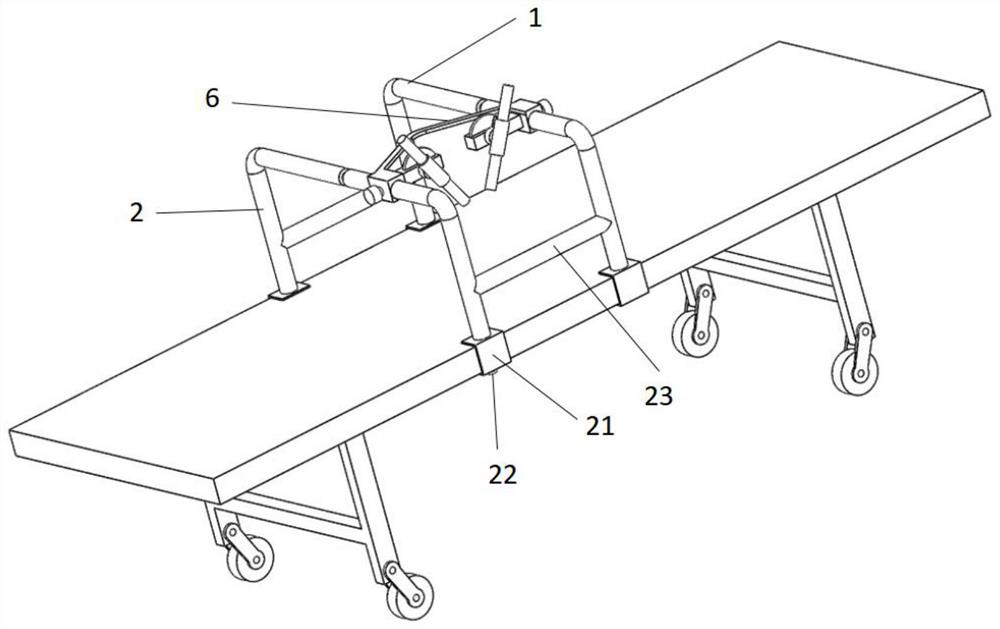
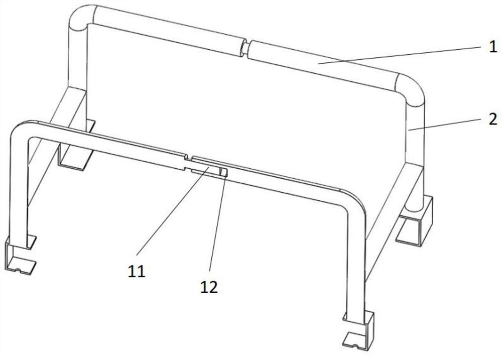
[0056] A single stent-type UBE surgical channel establishment instrument, refer to figure 1 ; It includes a support structure fixedly arranged on an operating bed or an exercise platform, and the support structure includes two parallel setting rods 1 for setting up the structure; the support structure also includes a plurality of support legs 2 supporting the setting rod 1; each set A channel building structure is set on the rod 1; the channel building structures are connected through the connecting structure 6, and the two channel building structures are provided with a sleeve guide structure 4, and the two sleeve guide structures 4 can be rotated on the channel building structure The angle is adjusted, and the two cannula guiding structures 4 guide the cannula to establish a surgical channel on the same channel establishment plane, and the two cannula guiding structures 4 are set on the same channel establishment plane through the connecting structure 6 . This kind of settin...

Embodiment 2

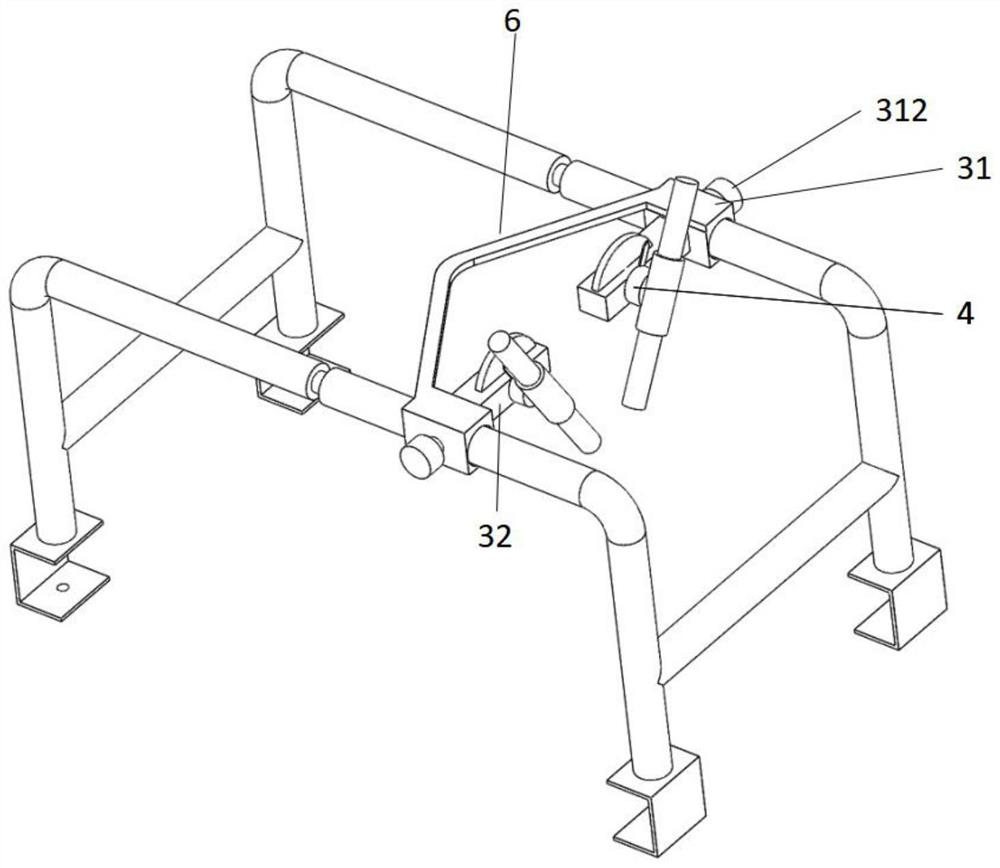
[0058] Set the specific structure of the channel establishment structure, specifically: refer to Figure 4 The channel building structure includes a moving section 31 with a moving hole 311 that is consistent with the diameter of the setting rod 1; the channel building structure is sleeved on the setting rod 1 through the moving hole 311, and a locking structure 312 is provided outside the moving section 31 , by setting the locking structure to achieve locking when it reaches a suitable position. The locking structure one 312 is the locking screw 22 .

[0059] One side of the moving section 31 protrudes from the setting section 32 of the guiding structure; the setting section 32 is provided with a through rotating hole 321, and the sleeve guide structure 4 stretches out a rotating rod 41, and the rotating rod 41 stretches into the rotating hole 321 and rotates The hole 321 protrudes, the first end of the rotating rod 41 is the casing guide structure 4, and the second end of t...

Embodiment 3

[0070] On the basis of embodiment 1 or 2, refer to Figure 1-3 ; The connection mode and number of the support leg 2 and the setting rod 1 are specifically set, specifically: the edge of the support leg 2 and the setting rod 1 are integrally connected with the setting rod 1, and the two setting rods 1 are provided with 4 support legs 2, 4 and support The leg 2 setup is more stable.

[0071] To increase the structure of the fixed support leg 2, one way is to set a support chassis with a larger area than the support leg 2 at the bottom of the support leg 2; Stable placement on the operating table or practice platform.

[0072] The second method is: the support structure is fixed on the edge of the operating bed or the practice platform, and the bottom end of the support leg 2 is provided with a bayonet 21 that can be locked. A threaded hole is provided at the bottom of the bayonet socket 21, and a locking screw 22 is provided in the threaded hole.

[0073] The embodiment of a...


PUM


Abstract

A single support type UBE operation channel establishing instrument comprises a supporting structure fixedly arranged on an operation bed or an exercise platform, and the supporting structure comprises two parallel arrangement rods; the supporting structure further comprises a plurality of supporting legs for supporting the setting rod; a channel building structure is arranged on each setting rod; the channel establishing structures are integrally connected through a connecting structure, the two channel establishing structures are each provided with a cannula guiding structure, the two cannula guiding structures can rotate on the channel establishing structures to adjust the angle, and the two cannula guiding structures guide a cannula to establish an operation channel on the same channel establishing plane. The channel building structure comprises a moving section combined with the setting rod and a setting section extending out of the moving section, and a sleeve guide structure is arranged on the setting section; and a rotating dial and a rotating pointer which are used for reading a rotating angle are arranged. Through the arrangement, the purposes that the angle of the sleeve guide structure is adjusted according to needs, and entering is conducted on one plane can be well achieved.

Description

technical field [0001] The invention belongs to the technical field of medical instruments, and in particular relates to an instrument for establishing a single-stent type UBE operation channel. Background technique [0002] UBE surgery is a unilateral dual-channel endoscopic technique, which is a kind of vertebral body surgery. Percutaneous observation and operation channels are respectively established through two small incisions on one side of the posterior approach, and endoscopes are placed in the observation channels to monitor the surgical field of view. Mirror instruments, and operating tools are placed in the operating channel for surgical operations inside and outside the spinal canal. Because of its good surgical field of view, this kind of surgery is currently being promoted in clinical practice. [0003] However, before the operation, cannulas of different calibers need to be obliquely entered at the two incisions and converged under the skin to establish an ef...

Claims


Application Information

Patent Timeline
IPC IPC(8): A61B17/00A61B90/50
Inventor 杨承刚肖枫陈丽媛常鹏孙耀兰张冬梅王李娜张珊珊
Owner GUAN BOJIAN BIOTECH CO LTD
Learn More