Check patentability & draft patents in minutes with Patsnap Eureka AI!

Intelligent combined numerical control machine tool

A CNC machine tool and compound technology, applied to metal processing machinery parts, manufacturing tools, other manufacturing equipment/tools, etc., can solve the problems of inconvenient parts processing, reduced equipment processing efficiency, troublesome switching, etc., and achieve simple equipment structure Effect

Active Publication Date: 2022-04-08
泉州市闽达机械制造有限公司
View PDF7 Cites 0 Cited by
  • Summary
  • Abstract
  • Description
  • Claims
  • Application Information

AI Technical Summary

Benefits of technology

This patented technology allows for easy loading multiple tools into different spaces inside an apparatus without having them protruding from its surface. It also makes it easier to use this equipment with various types of workpieces that require specialized tools like drilling bits or grinding wheels.

Problems solved by technology

This patented technical solution described by the inventors relates to improving machining performance when replacing or installing tools on complex machines with separate devices. However, there may still be difficulties during these processes because they require moving around from one part to another while changing tools.

Method used


Image

  • Intelligent combined numerical control machine tool
  • Intelligent combined numerical control machine tool
  • Intelligent combined numerical control machine tool

Examples


Embodiment Construction

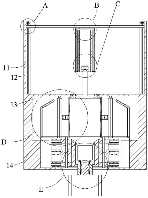
[0027] like Figure 1-Figure 8 As shown, the present invention is described in detail. For the convenience of description, the orientations mentioned below are now stipulated as follows: figure 1 The up, down, left, right, front and back directions of the projection relationship itself are consistent. An intelligent compound numerical control machine tool of the present invention includes a box body 14, and an internal cavity 13 is arranged in the box body 13, and left and right symmetrical Moving the clamping block 81, the moving clamping block 81 is provided with an open inner chamber 89, one side of the inner chamber 89 is communicated with a guide groove 90, and the inner chamber 13 is provided with a Groove 55, the bottom cavity 87 is communicated in the end wall of the inner cavity 13 passing through the opposite side of the groove 55, and a symmetrical inner groove 54 is arranged in the box body 14 at the top of the inner cavity 13. A rear motor 91 is arranged in the e...


PUM


Abstract

The intelligent combined type numerical control machine tool comprises a box body, an inner cavity is formed in the box body, movable clamping blocks which are in bilateral symmetry are arranged in the inner cavity, placing inner cavities with openings are formed in the movable clamping blocks, guide grooves are formed in one sides of the placing inner cavities in a communicating mode, and penetrating grooves are formed in the inner cavity. A penetrating groove is formed in the end wall, opposite to the penetrating groove, of the inner cavity in a communicating mode, a bottom cavity is formed in the end wall, opposite to the penetrating groove, of the inner cavity in a communicating mode, symmetrical inner grooves are formed in the positions, at the top of the inner cavity, of the box body, and rear side motors are arranged in the end walls of the inner grooves. The needed cutter can be clamped to one side of the movable clamping block after stretching out, the cutter can rotate to achieve the milling function, and the cutter can be kept fixed to achieve the turning function when the cutter is of a turning tool structure.

Description


Claims


Application Information

Patent Timeline
Owner 泉州市闽达机械制造有限公司
Features
  • R&D
  • Intellectual Property
  • Life Sciences
  • Materials
  • Tech Scout
  • Unparalleled Data Quality
  • Higher Quality Content
  • 60% Fewer Hallucinations
Learn More