Connecting structure for machining driving motor shaft

A technology for connecting structures and driving motors, which is applied to metal processing machinery parts, metal processing, metal processing equipment, etc., can solve the problems of reduced motor life, low efficiency of motor shafts, and many times of motor start-up, so as to speed up mass production, The effect of speeding up efficiency

Active Publication Date: 2022-04-08
浙江迅达工业科技股份有限公司
View PDF9 Cites 0 Cited by
  • Summary
  • Abstract
  • Description
  • Claims
  • Application Information

AI Technical Summary

Problems solved by technology

[0002]The connection structure of the processing drive motor shaft currently on the market can only connect one shaft. Clamp disassembly, mass production of motor shafts of the same specification is inefficient, and when the motor shafts are processed one by one, the motor that drives the connecting structure to rotate is replaced with a new motor shaft after each motor shaft is processed. It needs to be started once. During mass production, the motor starts more times, which reduces the service life of the motor

Method used


Image

  • Connecting structure for machining driving motor shaft
  • Connecting structure for machining driving motor shaft
  • Connecting structure for machining driving motor shaft

Examples


Embodiment 1

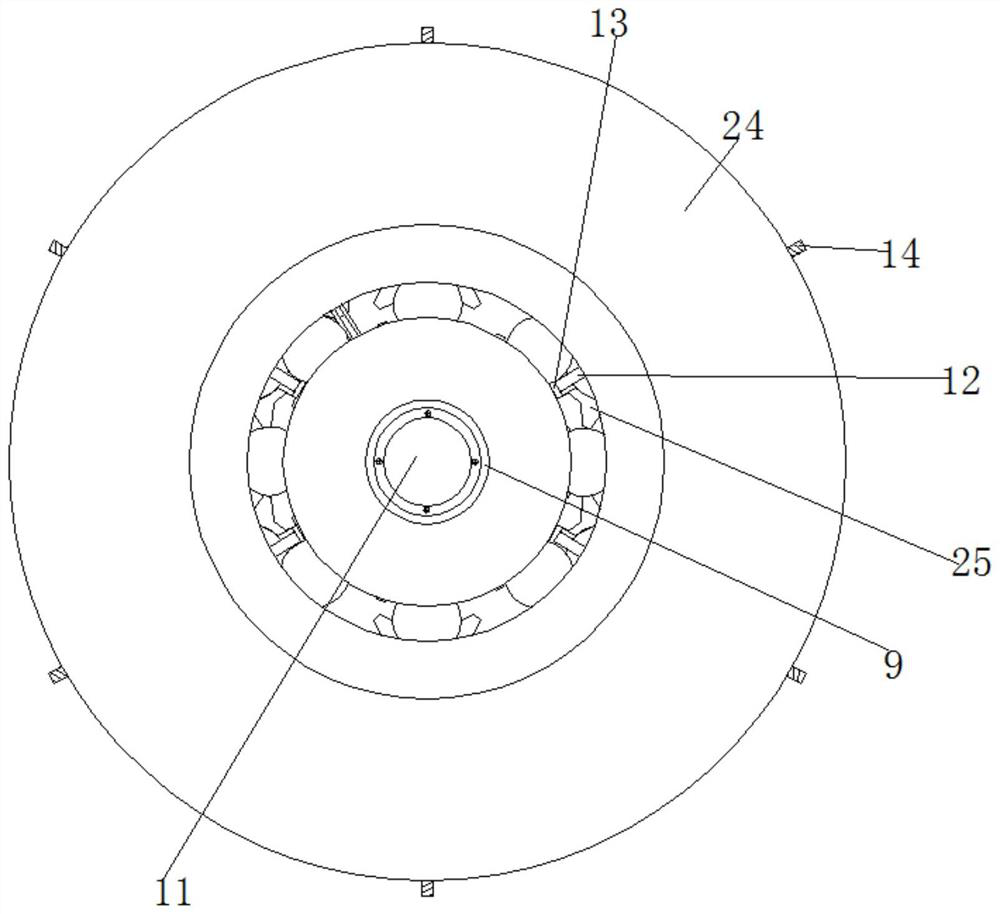
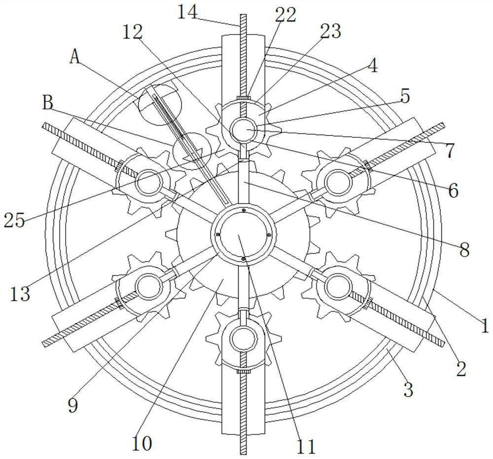
[0030] see figure 1 , figure 2 , image 3 , Figure 4 , Figure 5 , Figure 6 , Figure 7 , a connection structure for processing drive motor shafts, including an outer cylinder 1, an annular groove 2 is opened on the front and back of the outer cylinder 1, an annular frame 3 is slidably connected to the inside of the annular groove 2, and a connecting frame 3 is fixedly connected to the outer side of the annular frame 3 The inner side of the connecting frame is fixedly connected with a straight rod 8, and the end of the straight rod 8 away from the connecting frame is fixedly connected with a transmission device. Adjustment device.

[0031] The connecting frame consists of a U-shaped frame 4 and a driven tooth surface rotating cylinder 25. There is an insertion hole 5 between the front and the back of the U-shaped frame 4, and the driven tooth surface rotating cylinder 25 is movably inserted into the insertion hole 5. , the fixed connection part with the ring frame 3 ...

Embodiment 2

[0036] see figure 2 , Figure 5 , The fronts of the U-shaped frame 4 and the straight rod 8 are fixedly connected with a clamping device.

[0037] The clamping device comprises a fixed head 13, a moving head 23, a clamping connecting rod 12, a threaded rod 14 and a clamping nut 22, and the clamping connecting rod 12 and the threaded rod 14 are fixedly connected with the outer wall of the driven tooth surface drum 25, and the clamping One end of the tight connecting rod 12 away from the driven tooth surface drum 25 is fixedly connected with the fixed head 13. The threaded rod 14 runs through the moving head 23. Clamp nut 22.

[0038] By rotating the clamping nuts 22 at different positions, the multiple clamping nuts 22 are moved to different positions respectively, so as to achieve the effect of multiple paired moving heads 23 and fixed heads 13 clamping motor shafts of different specifications, thereby realizing Start the motor 11 at one time to realize the function of pro...

Embodiment 3

[0040] see figure 1 , figure 2 , Figure 5 , the tooth surface of the outer wall of the clamping nut 22 is meshed with the bottom tooth surface drum 24, the bottom tooth surface drum 24 is fixedly socketed with the active tooth surface drum 10 through the ball bearing, and the inner side of the bottom tooth surface drum 24 is The extreme position is located outside when the clamping nut 22 is at the innermost side.

[0041] By rotating the bottom tooth surface drum 24, the multiple clamping nuts 22 engaged with the bottom tooth surface of the bottom tooth surface drum 24 are driven to rotate. The threaded surface of the inner wall of the clamping nut 22 is threadedly connected with the threaded rod 14, so that the clamping nut 22 moves along the threaded rod 14 during the rotation, so that the multiple moving heads 23 can be moved in the same direction along the threaded rod 14. Adjustment, so as to realize the adjustment of the distance between the multiple moving heads 2...


PUM


Abstract

The invention relates to the technical field of motor shafts, and discloses a connecting structure for machining a driving motor shaft, which comprises an outer cylinder, and a plurality of clamping nuts meshed with the bottom tooth surface of a bottom tooth surface rotating cylinder are driven to rotate by rotating the bottom tooth surface rotating cylinder, so that the clamping nuts move along a threaded rod in the rotating process; the multiple movable heads can be adjusted in the same direction along the threaded rod, the effect that multiple machining shafts can be clamped or disassembled at the same time is achieved, the efficiency of batch production is improved, the multiple clamping nuts are moved to different positions by rotating the clamping nuts at different positions, and the machining efficiency is improved. Therefore, the effect that the multiple moving heads and the multiple fixed heads which are used in pairs clamp motor shafts of different specifications is achieved, the function of machining the multiple motor shafts by starting the motor at a time is achieved, the starting frequency of the motor is reduced under the condition that the same number of machining shafts are machined, and the service life of the motor is prolonged.

Description

technical field [0001] The invention relates to the technical field of motor shafts, in particular to a connection structure for machining and driving motor shafts. Background technique [0002] The connection structure of the processing drive motor shafts currently on the market can only connect one shaft. When the motor shafts of the same specification need to be processed in batches, they can only be clamped and disassembled one by one. The efficiency of mass production of the motor shafts of the same specification is low. When the motor shafts are processed one by one, the motor that drives the connecting structure to rotate will need to be started once when each motor shaft is processed and replaced with a new motor shaft. During mass production, the motor starts more times, reducing the the service life of the motor. Contents of the invention [0003] (1) Solved technical problems [0004] Aiming at the deficiencies of the prior art, the present invention provides ...

Claims


Application Information

Patent Timeline
Patent Type & Authority Applications(China)
IPC IPC(8): B23Q3/00B23Q7/00
Inventor 王红宇陈少武李贵铭刘忠云蒋和江
Owner 浙江迅达工业科技股份有限公司
Why Eureka
Try Eureka