
Material cutting mechanism of injection mold

A technology of injection mold and mold cavity, which is applied in the field of injection mold material breaking mechanism, and can solve problems such as complex mold structure

Pending Publication Date: 2022-04-08
NINGBO FANGZHENG TOOL
View PDF0 Cites 0 Cited by
  • Summary
  • Abstract
  • Description
  • Claims
  • Application Information

AI Technical Summary

Problems solved by technology

[0003] Injection molded products usually need to use the thimble structure to realize the ejection and demoulding of the product. The existing injection molded products usually need to carry out a material breaking process of the injection head after the product is demoulded before demoulding; The structure of the mold is optimized accordingly, that is, the injection plastic head of the product is automatically cut off before the product is demoulded, and then the product is demoulded, thereby saving the process of breaking the material after demoulding, but the existing ones with The mold with broken material structure becomes very complicated due to the addition of cutting function, and how to take out and collect the material head after cutting is also a problem

Method used


Image

  • Material cutting mechanism of injection mold
  • Material cutting mechanism of injection mold
  • Material cutting mechanism of injection mold

Examples


Embodiment Construction

[0029] In order to make the above objects, features and advantages of the present invention more comprehensible, specific embodiments of the present invention will be described in detail below in conjunction with the accompanying drawings.

[0030] In the description of the present invention, it should be noted that the orientation or positional relationship indicated by the terms "upper end", "lower end", "inner wall" and "outer wall" are based on the orientation or positional relationship shown in the drawings, and are only for It is convenient to describe the present invention and simplify the description, but does not indicate or imply that the device or element referred to must have a specific orientation, be constructed and operate in a specific orientation, and thus should not be construed as limiting the present invention. In addition, in the description of the present invention, the terms "first" and "second" are only for convenience of description and distinction, and...


PUM


Abstract

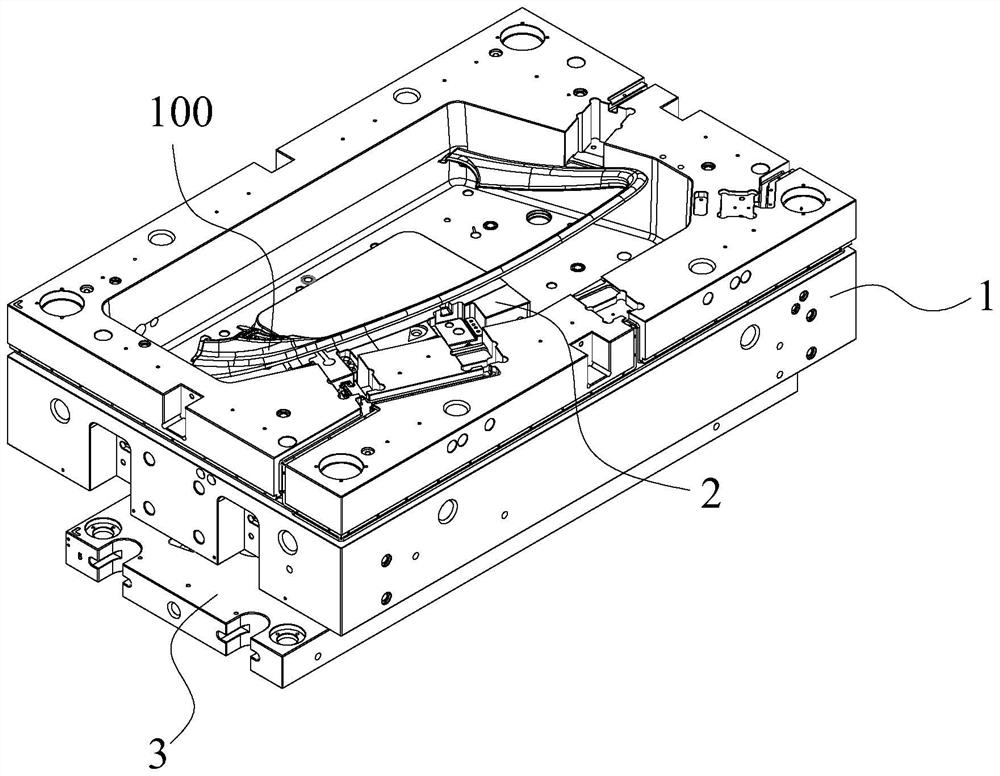
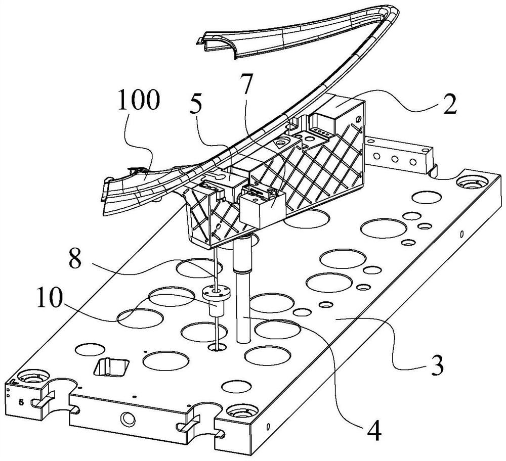
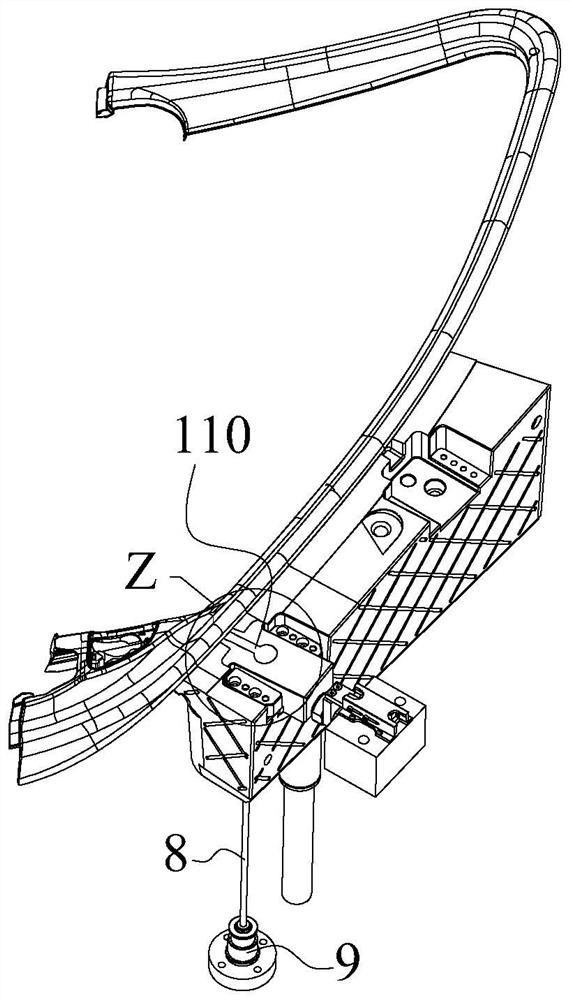
The invention provides an injection mold material cutting mechanism which comprises a fixed mold block, a large sliding block is arranged on the fixed mold block in a sliding mode, an ejector plate is arranged below the fixed mold block, an ejector rod used for driving the large sliding block to slide is arranged on the ejector plate, a small sliding block is arranged on the large sliding block in a sliding mode, and a feeding runner communicated to a mold cavity is arranged on the small sliding block. A driving cylinder used for driving the small sliding block to be separated from the large sliding block is arranged on the fixed mold block, so that material cutting of a material head in the feeding runner and a product in the mold cavity is achieved; the ejector plate is further provided with an ejector rod and a driving assembly in a sliding mode, wherein the driving assembly is used for driving the ejector rod to eject and drive the stub bar to be separated from the feeding runner. According to the material cutting mechanism of the injection mold, rapid separation of an injection product and a material head can be achieved, the separated material head can be effectively separated from the runner, and the demolding efficiency is improved.

Description

technical field [0001] The invention relates to the technical field of injection molds, in particular to an injection mold cutting mechanism. Background technique [0002] Injection mold is a tool for producing plastic products, and it is also a tool for giving plastic products complete structure and precise dimensions. Injection molding is a processing method used in the mass production of certain complex-shaped parts. Specifically, it refers to injecting heated and melted plastic into a mold cavity under high pressure from an injection molding machine, and after cooling and solidifying, a molded product is obtained. [0003] Injection molded products usually need to use the thimble structure to realize the ejection and demoulding of the product. The existing injection molded products usually need to carry out a material breaking process of the injection head after the product is demoulded before demoulding; The structure of the mold is optimized accordingly, that is, the ...

Claims


Application Information

Patent Timeline
IPC IPC(8): B29C45/38B29C45/26B29C45/40
Inventor 应军杰王一栋俞方敏赵超锋黄伟林晨锋黄志高周华民
Owner NINGBO FANGZHENG TOOL
Learn More