Supercharge Your Innovation With Domain-Expert AI Agents!

Measuring and positioning tool for oral implantation

A tool and oral technology, which is applied in the field of oral implant measurement and positioning tools, can solve the problems of unfavorable positioning accuracy, inconvenience for widespread use, and inability to implant positions, and achieves the effects of easy operation, cost savings, and improved measurement efficiency.

Pending Publication Date: 2022-04-12
周口市第一人民医院
View PDF0 Cites 0 Cited by
  • Summary
  • Abstract
  • Description
  • Claims
  • Application Information

AI Technical Summary

Problems solved by technology

[0003] When implanting a patient’s teeth, it is necessary to determine the implantation point in advance. However, most of the traditional methods of collecting implantation points use the implant positioning ruler to locate the implant position. When positioning, the implant positioning ruler is inserted into the area to be implanted. Between the two adjacent teeth in the area to be implanted, read the distance between the two adjacent teeth according to the scale on the implant positioning ruler, and calculate the middle position between the two adjacent teeth as the positioning position according to the distance , but because it requires multiple data supports for calculation, not only the operation is inconvenient, but also the implant position cannot be intuitively displayed in the oral cavity, which is not conducive to the accuracy of positioning, and some smart devices are used for 3D modeling Acquisition and positioning. Although this method has high precision, it is expensive and not easy to be widely used. Therefore, a dental implant measurement and positioning tool is proposed.

Method used


Image

  • Measuring and positioning tool for oral implantation
  • Measuring and positioning tool for oral implantation
  • Measuring and positioning tool for oral implantation

Examples


Embodiment Construction

[0033] The following will clearly and completely describe the technical solutions in the embodiments of the present invention with reference to the drawings in the embodiments of the present invention. Based on the embodiments of the present invention, all other embodiments obtained by persons of ordinary skill in the art without making creative efforts belong to the protection scope of the present invention.

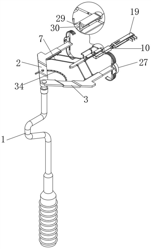
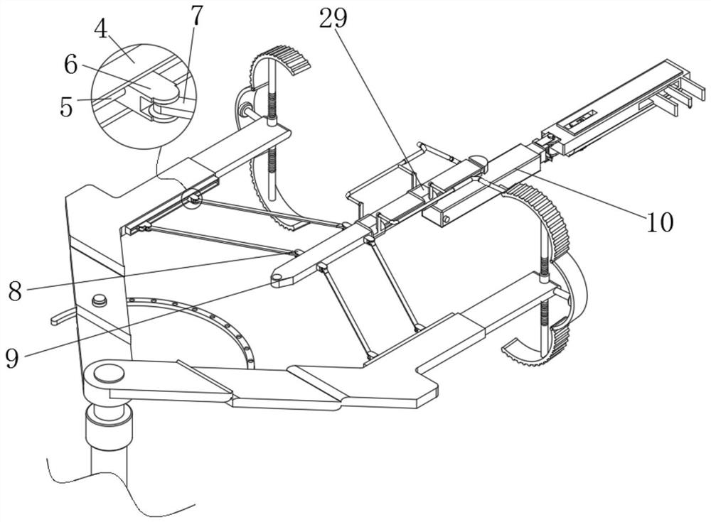
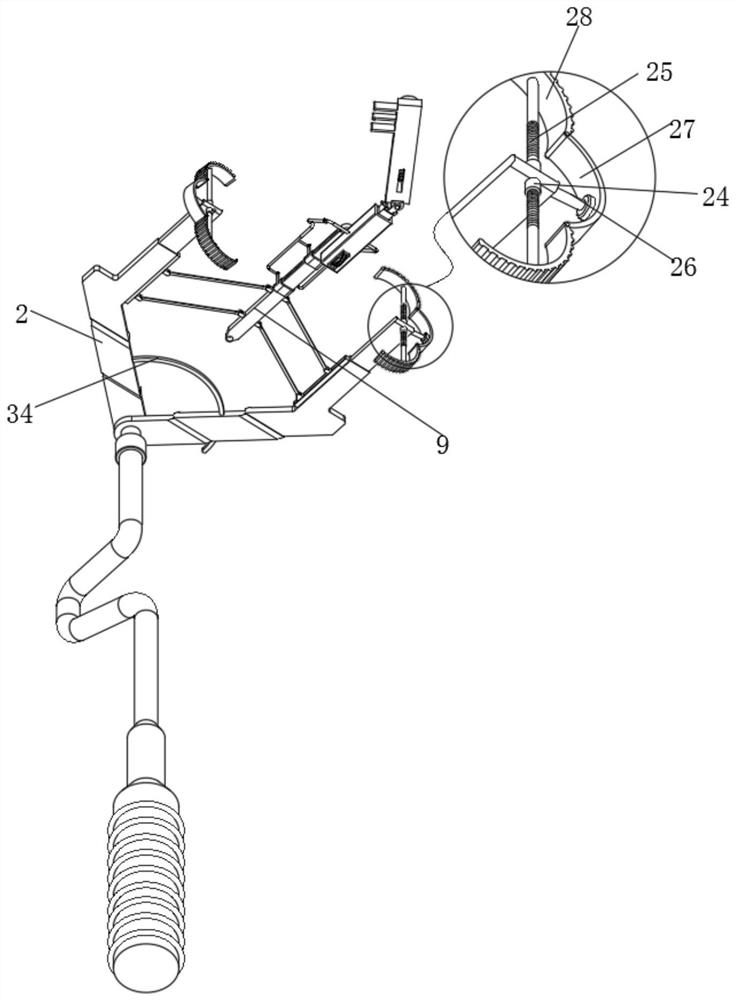
[0034] see Figure 1 to Figure 8 , the present invention provides a technical solution: a dental implant measurement and positioning tool, including a handle 1, which facilitates the holding and use of the tool, and the upper surface of the handle 1 is respectively movably mounted with a first side plate 2 and second side plate 3;

[0035] The surface of the second side plate 3 is fixedly connected with an adjusting ring 34, the surface of the first side plate 2 is provided with a through groove suitable for the adjusting ring 34, and the upper surface of the first sid...


PUM


Abstract

The invention relates to the technical field of oral cavities, and discloses an oral implant measuring and positioning tool which comprises a grip, a first side plate and a second side plate are movably mounted on the upper surface of the grip through pin shafts, and opening mechanisms are arranged on the surfaces of the first side plate and the second side plate. And the opposite sides of the first side plate and the second side plate are fixedly connected with fixed seats. According to the oral implant measuring and positioning tool, through cooperative use of an auxiliary mechanism and a measuring mechanism, a guide plate and a measuring plate are placed on the two sides of adjacent teeth needing to be implanted, a main gear is rotated to drive an auxiliary gear on the main gear to rotate, and through the proportional structural design of the main gear and the auxiliary gear, when the measuring plate moves, the measuring plate can be accurately positioned; the positioning plate only moves by half of the moving distance of the measuring plate, so that the midpoint between the guide plate and the measuring plate can be displayed at any time, the planting point can be positioned more visually, meanwhile, the cost is saved, and popularization and application are facilitated.

Description

technical field [0001] The invention relates to the field of oral cavity technology, in particular to an oral cavity implant measuring and positioning tool. Background technique [0002] The oral cavity is the beginning of the digestive tract. The anterior cleft communicates with the outside world, and the posterior pharynx connects with the pharynx. There are teeth, tongue and other organs in the oral cavity. The front wall of the oral cavity is the lips, the side wall is the cheek, the top is the palate, The floor of the oral cavity is composed of mucous membranes and muscles. The oral cavity is divided into the anterolateral oral vestibule and the posteromedial oral cavity by means of the upper and lower dental arches. The gap behind the third molars is connected. Clinically, when the patient's trismus is closed, a gag or cannula can be placed through this passage to inject drugs or nutrients while preventing tongue bite. [0003] When implanting a patient’s teeth, it is...

Claims


Application Information

Patent Timeline
IPC IPC(8): A61C8/00A61C19/04
Inventor 赵新宇马书娜
Owner 周口市第一人民医院
Features
  • R&D
  • Intellectual Property
  • Life Sciences
  • Materials
  • Tech Scout
  • Unparalleled Data Quality
  • Higher Quality Content
  • 60% Fewer Hallucinations
Learn More