Automatic fire extinguishing system based on multi-dimensional perception triggering

An automatic fire extinguishing system and automatic fire extinguishing technology, applied in the field of safety systems, can solve problems such as waste of installation time, cumbersome installation, and misreporting, and achieve the effect of eliminating electrical fire accidents and improving safety management

Active Publication Date: 2022-04-12
浙江万立宏科技有限公司
View PDF7 Cites 0 Cited by
  • Summary
  • Abstract
  • Description
  • Claims
  • Application Information

AI Technical Summary

Problems solved by technology

In order to avoid fires caused by circuit failures, it is necessary to be equipped with a variety of monitoring devices, such as smoke monitoring, flame monitoring, temperature monitoring, current monitoring, etc., so that the adaptability between monitoring devices and monitoring devices needs to be considered. There are incompatibility phenomena between them, and false positives and false positives are easy to occur. Not only that, but multiple installations are required in multiple locations, resulting in cumbersome installation and wasting unnecessary installation time.
[0003] In addition, the current automatic fire extinguishing device is at the initial stage of a fire, and the temperature in the space continues to rise accordingly. When the temperature rises to the point where the temperature sensing element of the closed nozzle explodes or melts and falls off, the nozzle will automatically spray water to extinguish the fire. After the component is blasted, it needs to be reconfigured before it can be used again, making its operation cumbersome

Method used


Image

  • Automatic fire extinguishing system based on multi-dimensional perception triggering
  • Automatic fire extinguishing system based on multi-dimensional perception triggering
  • Automatic fire extinguishing system based on multi-dimensional perception triggering

Examples


Embodiment Construction

[0034] The present invention will be described in further detail below in conjunction with the accompanying drawings and embodiments. Wherein the same components are denoted by the same reference numerals. It should be noted that the words "front", "rear", "left", "right", "upper" and "lower" used in the following description refer to the directions in the drawings, and the words "bottom" and "top "Face", "inner" and "outer" refer to directions toward or away from, respectively, the geometric center of a particular component.

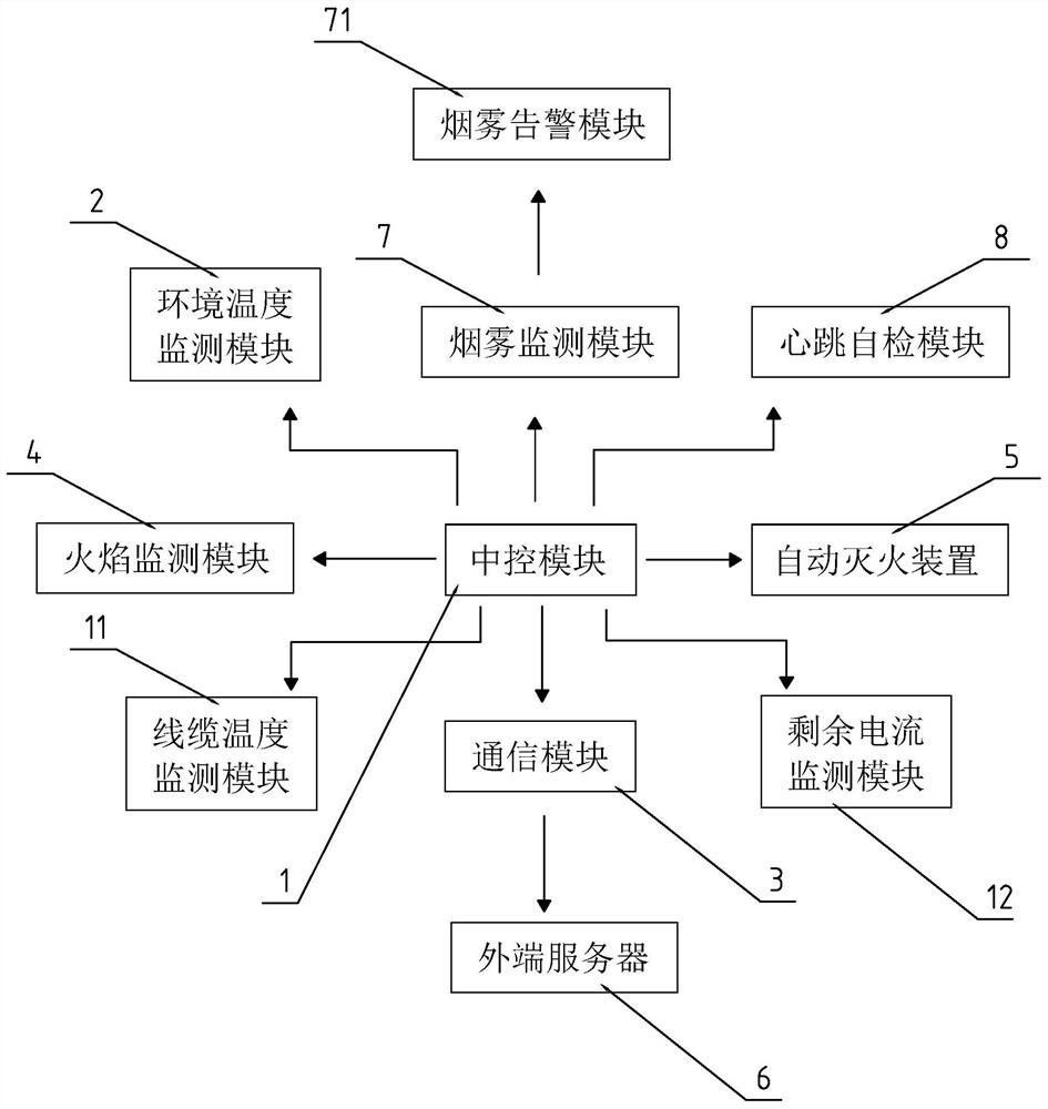
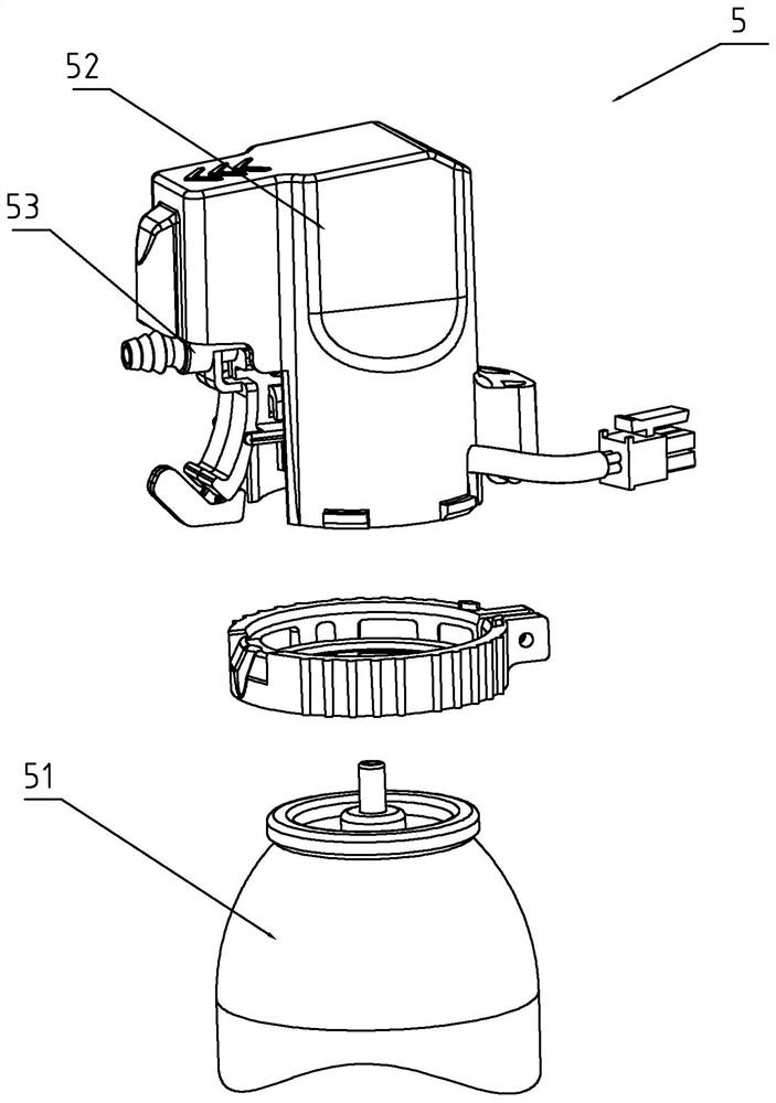
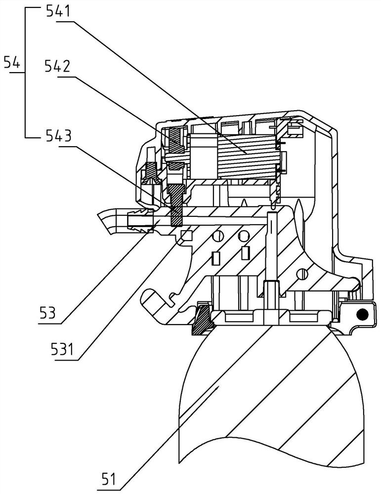
[0035] refer to Figure 1 to Figure 6 As shown, in order to achieve the above object, the present invention provides the following technical solutions: an automatic fire extinguishing system based on multi-dimensional perception triggering, including a central control module 1, an ambient temperature monitoring module 2, a communication module 3, a flame monitoring module 4, an automatic The fire extinguishing device 5, and the external server 6 (back...


PUM


Abstract

According to the technical scheme, the automatic fire extinguishing system is characterized by comprising a central control module, an environment temperature monitoring module, a communication module, a flame monitoring module, an automatic fire extinguishing device and an outer end server, the environment temperature monitoring module is used for collecting the nearby environment temperature in real time, and the communication module is used for communicating with the central control module; the flame monitoring module is used for capturing a flame signal, setting a flame time monitoring threshold value, and feeding back the flame signal to the outer end server when the duration time of the flame signal exceeds the flame time monitoring threshold value; the central control module is used for receiving the environment temperature signal and the flame signal, and when the environment temperature signal and the flame signal coexist, the central control module sends a fire extinguishing signal to the automatic fire extinguishing device; the automatic fire extinguishing device performs fire extinguishing operation according to the fire extinguishing signal, and the automatic fire extinguishing system can integrate various monitoring and realize integrated monitoring operation, so that the effect is greatly improved, and the automatic fire extinguishing system can be repeatedly used.

Description

technical field [0001] The invention relates to a safety system, more specifically, it relates to an automatic fire extinguishing system triggered based on multi-dimensional perception. Background technique [0002] Fire safety is a top priority no matter what the venue. In order to avoid fires caused by circuit failures, it is necessary to be equipped with a variety of monitoring devices, such as smoke monitoring, flame monitoring, temperature monitoring, current monitoring, etc., so that the adaptability between monitoring devices and monitoring devices needs to be considered. There are incompatibility phenomena between them, and false positives and false positives are easy to occur. Not only that, but multiple installations are required in multiple locations, resulting in cumbersome installation and a waste of unnecessary installation time. [0003] In addition, the current automatic fire extinguishing device is at the initial stage of a fire, and the temperature in the ...

Claims


Application Information

Patent Timeline
Patent Type & Authority Applications(China)
IPC IPC(8): A62C37/00A62C31/02A62C31/28G08B17/06G08B17/10
Inventor 郑建龙朱敏徐国权王加瑜张俊王杰潘榕峰李旭郑贵
Owner 浙江万立宏科技有限公司
Why Eureka
Try Eureka