Tri-state separation and purification garbage treatment equipment
A garbage treatment equipment and rotary separation technology, which is applied in the separation method, dispersed particle separation, dispersed particle filtration, etc., can solve problems such as garbage classification, and achieve the effect of slowing down the degree of decay
- Summary
- Abstract
- Description
- Claims
- Application Information
AI Technical Summary
Problems solved by technology
Method used
Image
Examples
Embodiment 1
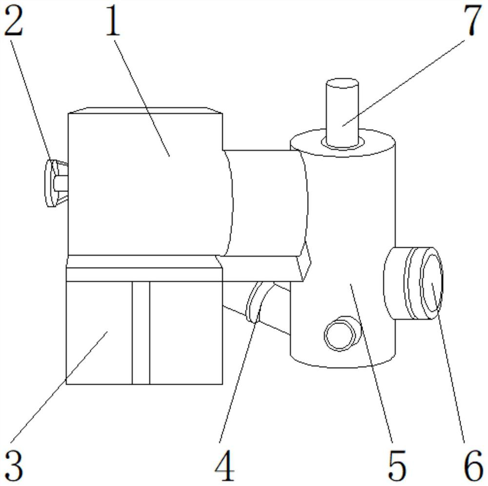
[0026] Such as Figure 1-4 As shown, the present invention provides a three-state separation and purification garbage treatment equipment, including a main body 1, a regulating valve 2 is arranged on one side of the main body 1, a rotating separation device 3 is arranged on the lower end of the main body 1, and one side of the rotating separation device 3 Cooling device 4 is provided, and one side of cooling device 4 is provided with cleaning cylinder 5, and the upper end of cleaning cylinder 5 is provided with purification device 7, and one side of cleaning cylinder 5 is provided with water outlet pipe 6; Purification device 7 comprises heating rod 701, drive Device 702, regeneration tank 703, filter cloth 704, condenser 705, desulfurization pipe 706, processing blower 707, driving device 702 is located at the upper end of heating rod 701, regeneration tank 703 is located at one side of heating rod 701; the upper end of heating rod 701 passes The notch is detachably connected...
Embodiment 2
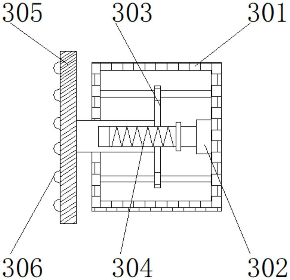
[0029] Such as Figure 1-4 As shown, on the basis of Embodiment 1, the present invention provides a technical solution: preferably, the rotary separation device 3 includes a frame 301, a threaded groove 302, an automatic heating pipe 303, a rotating shaft 304, an oil collecting tank 305, and an oil scraping block 306, the threaded groove 302 is located on the inner wall of the frame 301, the rotating shaft 304 is located on one side of the threaded groove 302, the automatic heating pipe 303 is located on the upper end of the rotating shaft 304, the oil collecting tank 305 is located on one side of the frame 301, and the oil scraping block 306 is located on the oil collecting tank 305, a welding block is arranged between the frame 301 and the thread groove 302, the inner wall of the frame 301 is fixedly connected with one side of the thread groove 302 through the welding block, a notch is arranged between the thread groove 302 and the rotating shaft 304, and the thread One side...
Embodiment 3
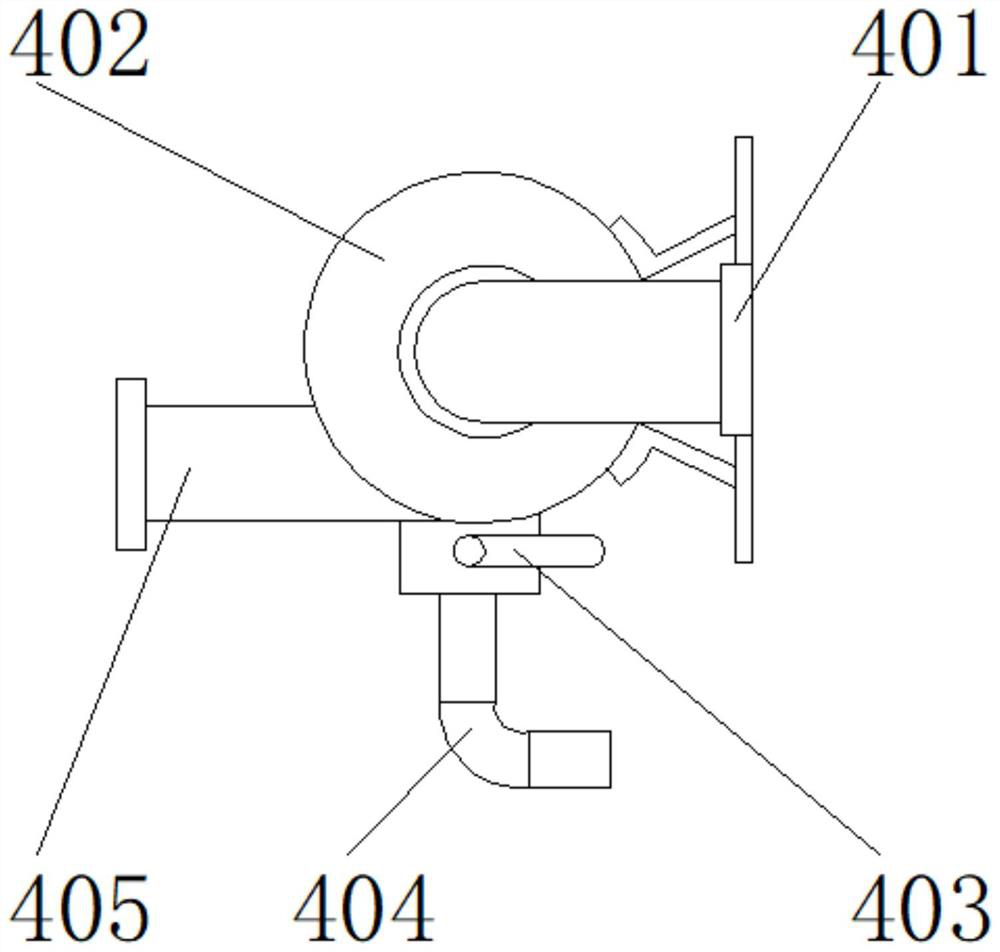
[0032] Such as Figure 1-4 As shown, on the basis of Embodiment 1, the present invention provides a technical solution: preferably, the cooling device 4 includes a mounting plate 401, a coolant expansion tank 402, a thermostat 403, a water pipe 404, a water pump 405, and the coolant expands The tank 402 is located on one side of the installation plate 401, the water pump 405 is located on the side of the coolant expansion tank 402, the thermostat 403 is located at the lower end of the coolant expansion tank 402, the water pipe 404 is located at the lower end of the thermostat 403, the installation plate 401 is connected to the cooling Bolts are arranged between the liquid expansion tanks 402, one side of the mounting plate 401 is fixedly connected to one side of the coolant expansion tank 402 by bolts, and one side of the water pump 405 is fixedly connected to the upper end of the water pipe 404 through a connection hole.
[0033] In this embodiment, it is possible to avoid th...
PUM
 Abstract
Description
Claims
Application Information
 - R&D
- Intellectual Property
- Life Sciences
- Materials
- Tech Scout
- Unparalleled Data Quality
- Higher Quality Content
- 60% Fewer Hallucinations
Browse by: Latest US Patents, China's latest patents, Technical Efficacy Thesaurus, Application Domain, Technology Topic, Popular Technical Reports.
© 2025 PatSnap. All rights reserved.Legal|Privacy policy|Modern Slavery Act Transparency Statement|Sitemap|About US| Contact US: help@patsnap.com


