End socket edge cutting device and method

A head and cutting torch technology, applied in auxiliary devices, welding/cutting auxiliary equipment, auxiliary welding equipment, etc., can solve problems such as edge cutting, and achieve the effect of improving efficiency

Pending Publication Date: 2022-04-12
XI AN RAILWAY TRANSPORTATION EQUIP
View PDF0 Cites 0 Cited by
  • Summary
  • Abstract
  • Description
  • Claims
  • Application Information

AI Technical Summary

Problems solved by technology

[0003] Aiming at the defects and deficiencies in the prior art, the present invention provides a device and method for edge cutting of the head to solve the problem of edge cutting after the head is formed

Method used


Image

  • End socket edge cutting device and method
  • End socket edge cutting device and method
  • End socket edge cutting device and method

Examples


Embodiment 1

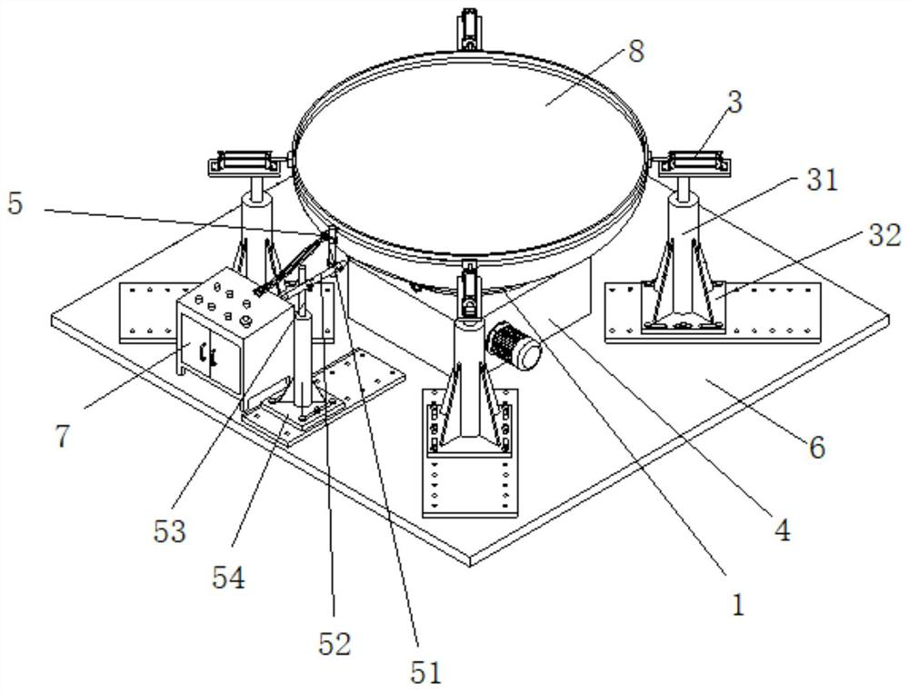
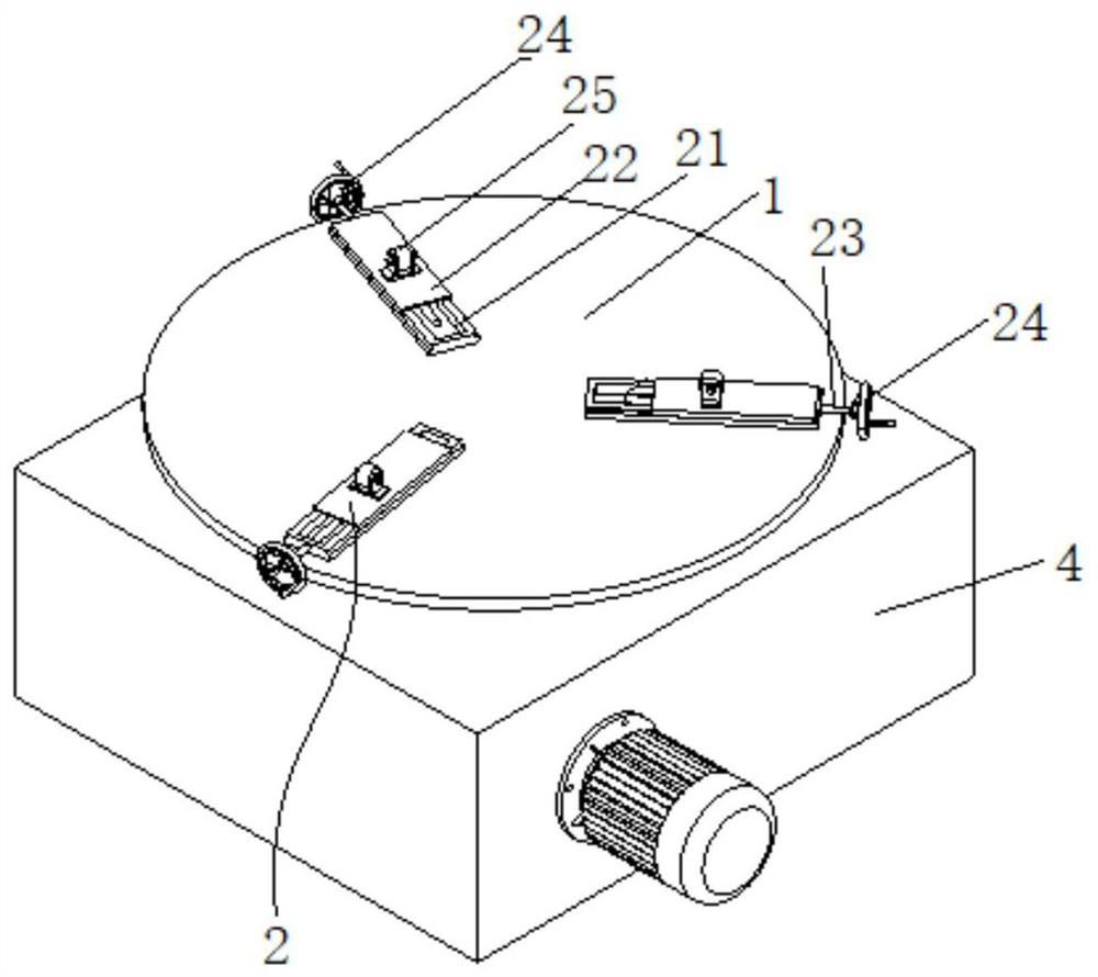
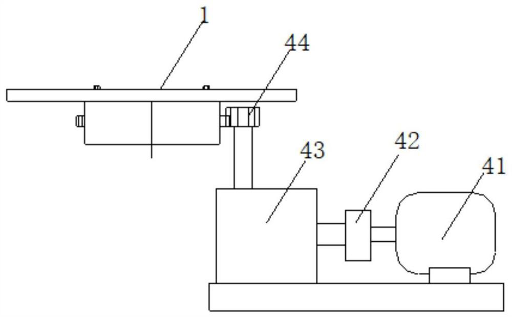
[0030] This embodiment provides a head edge cutting device, such as Figure 1 to Figure 3 As shown, it includes a head support disc 1, an alignment fine-tuning assembly 2 arranged on the head support disc 1, a plurality of cylinders 3 arranged around the head support disc 1, and a plurality of cylinders 3 arranged under the head support disc 1 The transmission system 4 and the torch 5 located next to the head support disc 1.

[0031] The head can be placed on the head support disc 1, and the alignment fine-tuning assembly 2 can assist the head to perform preliminary horizontal alignment by using its own weight. A plurality of cylinders 3 are evenly distributed along the circular track and the circular track is aligned with the head support disc. 1 is coaxial, and each cylinder 3 can expand and contract radially along the circular trajectory, and the protruding end of the piston rod of each cylinder 3 can be supported on the straight edge of the head so that the head moves towa...

Embodiment 2

[0041] This embodiment provides a head edge cutting method, which is realized by the head edge cutting device in Example 1. The method includes the following steps: Step 1: Drop the head onto the head support disc with a crane , the alignment fine-tuning component can assist the head to perform preliminary horizontal alignment by its own weight; Step 2: Start the cylinder, and multiple cylinders will move synchronously to the center of the head to push the head to be aligned; Step 3: Turn off the power supply of the cylinder to reset the cylinder; Step 4: Use the fine-tuning function of the alignment and fine-tuning components to make the head completely horizontal; Step 5: Start the torch, and turn on the transmission system to drive the head support disc to rotate to cut the edge of the head.


PUM


Abstract

The invention discloses an end socket edge cutting device and method. The end socket edge cutting device comprises an end socket supporting disc, an alignment fine adjustment assembly, a plurality of air cylinders, a transmission system and a cutting gun. A seal head can be placed on the seal head supporting disc, the alignment fine adjustment assembly can assist the seal head in conducting preliminary horizontal alignment through the dead weight, the multiple air cylinders are evenly distributed along a circular track, the circular track is coaxial with the seal head supporting disc, and each air cylinder can stretch out and draw back in the radial direction of the circular track. The extending end of a piston rod of each air cylinder can abut against the straight edge of the end socket to enable the end socket to move towards the center of the end socket supporting disc so that the end socket can be placed right, the transmission system can drive the end socket supporting disc to rotate, and meanwhile the cutting gun can cut the edge of the end socket. The end socket can be aligned for multiple times, and the edge cutting quality and efficiency are improved.

Description

technical field [0001] The invention belongs to the technical field of head manufacturing, and in particular relates to a head edge cutting device and method. Background technique [0002] The existing edge cutting of the head mainly uses placing the head on a horizontal platform for alignment and edge cutting. The disadvantages of the existing technology: (1) It is impossible to ensure that the head is placed on the horizontal platform (2) Generally, the head is placed on a horizontal platform Manually adding a wedge in the gap between the top and the platform to adjust the position of the head is inefficient, labor-intensive and has potential safety hazards. Contents of the invention [0003] Aiming at the defects and deficiencies in the prior art, the present invention provides a head edge cutting device and method to solve the edge cutting problem after the head is formed. [0004] To achieve the above object, the present invention takes the following technical soluti...

Claims


Application Information

Patent Timeline
Patent Type & Authority Applications(China)
IPC IPC(8): B23K7/00B23K7/10B23K37/04B23K37/047
Inventor 邹文杰王伟王建红范文革麻彬彬罗奥
Owner XI AN RAILWAY TRANSPORTATION EQUIP
Why Eureka
Try Eureka