Transformer substation reactive voltage control method and system

A voltage control method and substation technology, applied in reactive power compensation, AC network voltage adjustment, reactive power adjustment/elimination/compensation, etc., can solve the problem of inability to control reactive power and voltage of power grid substations, reduce system voltage quality and reactive power balance , system overcompensation and other issues

Active Publication Date: 2015-04-22
JIANGMEN POWER SUPPLY BUREAU OF GUANGDONG POWER GRID
View PDF5 Cites 0 Cited by
  • Summary
  • Abstract
  • Description
  • Claims
  • Application Information

AI Technical Summary

Problems solved by technology

[0004] VQC only takes the voltage and reactive power of a substation as the adjustment target, and it does not consider the voltage and reactive power of the grid system. Under certain conditions, the control object will be frequently operated, which will reduce the voltage quality and Reactive power balance will also increase the loss of capacitor switches and main transformer adjustment switches, and shorten their service life; although dynamic VQC has the function of fine-tuning voltage and reactive power, it only works for a single substation and cannot Substations in the area perform reactive power and voltage control
[0005] The AVC function calculates the optimal adjustment strategy by comprehensively considering the voltage and reactive power of substations with different voltage levels in the same area, and then controls the control objects of each substation in the area. However, since the capacitor variable is a fixed value, due to It is necessary to switch a whole group of capacitors each time, and sometimes the system will overcompensate after operation; when the system is in a critical state, there will be frequent switching, especially when the substation is in low-load operation. The situation will occur more frequently, affecting the stable operation of the substation
[0006] It can be seen that the existing voltage control methods cannot effectively control the reactive voltage of the grid substation.

Method used


Image

  • Transformer substation reactive voltage control method and system
  • Transformer substation reactive voltage control method and system
  • Transformer substation reactive voltage control method and system

Examples


Embodiment Construction

[0046] The present invention will be described in detail below in conjunction with the accompanying drawings.

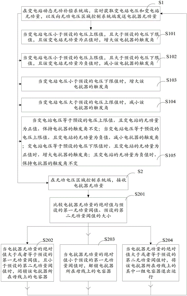
[0047]A substation reactive voltage control method proposed by the present invention, its implementation process can refer to figure 1 , including: a processing process at the substation dynamic reactive power compensation system (VQC), specifically including steps S1 to S105; and a processing process at the reactive voltage area control system (AVC) end, specifically including steps S2 to S204;

[0048] S1. At the substation dynamic reactive power compensation system end, obtain the substation voltage and substation reactive power in real time; and upload the reactor reactive power to the reactive voltage area control system;

[0049] S101. When the substation voltage is less than the preset voltage upper limit and greater than the preset voltage lower limit, and the reactive power of the substation is a positive value, increase the firing angle of the reactor;

[...


PUM


Abstract

The invention provides a transformer substation reactive voltage control method which includes the following steps. Voltage and a reactive value of a transformer substation are obtained in real time; a reactive value of an electric reactor is uploaded; the way to adjust a triggering angle of the electric reactor is confirmed based on the voltage of the transformer substation, a preset voltage upper limit value and a preset voltage lower limit value; the reactive value of the transformer substation is received; whether a capacitor on a bus where the electric reactor exists is put or not is confirmed based on the reactive value of the transformer substation, a preset first reactive threshold value and a preset second reactive threshold value. The invention further provides a reactive voltage control system of the transformer substation so as to achieve regional reactive voltage control. Meanwhile, the function of finely tuning voltage reactive power is achieved so as to reduce operation times of the capacitor and a tapping point of a transformer to the utmost. Operational stability of the transformer substation is improved so as to effectively control reactive voltage of a grid transformer substation.

Description

technical field [0001] The invention relates to the field of substation reactive voltage control, in particular to a substation reactive voltage control method and system. Background technique [0002] In recent years, with the continuous expansion of the power grid and the increasing requirements of users for power quality, the research on the automatic control technology of reactive power and voltage of the power grid has been deepened at home and abroad, and various automatic control technologies of reactive power and voltage have emerged. This technology is mainly divided into two categories: one takes a single substation as the optimization object, and mainly controls the capacitor bank and the main transformer tap of the single substation to achieve the optimization of reactive power voltage. This type of technology is called reactive power voltage control. , referred to as VQC (Voltage Quality Control, voltage quality control) technology, this type of technology has a...

Claims


Application Information

Patent Timeline
Patent Type & Authority Patents(China)
IPC IPC(8): H02J3/18H02J3/16
CPCY02E40/34Y02E40/30
Inventor 黄国政欧郁强邱玩辉胡少强蔡德华周落星赖奎黄亮浩
Owner JIANGMEN POWER SUPPLY BUREAU OF GUANGDONG POWER GRID
Why Eureka
Try Eureka