
Rapid cooling injection mold and injection molding system thereof

A rapid cooling, injection mold technology, applied in the field of injection molds, can solve the problems of poor cooling efficiency, different cooling capacity, different accumulation of molten plastic, etc., to achieve the effect of improving cooling efficiency

Active Publication Date: 2022-04-12
江苏通工金属科技有限公司
View PDF6 Cites 0 Cited by
  • Summary
  • Abstract
  • Description
  • Claims
  • Application Information

AI Technical Summary

Problems solved by technology

[0004] However, there are still certain defects in the prior art, such as: 1, the coolant enters the cooling chamber through the inlet joint, the coolant flows in the cooling chamber to absorb heat, and the temperature of the coolant increases with the increase of the flow distance. After a long distance, the cooling effect of the cooling liquid becomes worse due to the temperature rise, which makes the cooling efficiency worse; 2. The accumulation amount of molten plastic in the mold is different, so that the cooling capacity required for each part of the product is also different, and a uniform flow rate is adopted The cooling liquid uniformly cools all parts of the product, so that the place where the molten plastic accumulates cannot be targeted and focused on cooling, resulting in a long cooling time for this part, and the effect of rapid cooling cannot be achieved

Method used


Image

  • Rapid cooling injection mold and injection molding system thereof
  • Rapid cooling injection mold and injection molding system thereof
  • Rapid cooling injection mold and injection molding system thereof

Examples


Embodiment 1

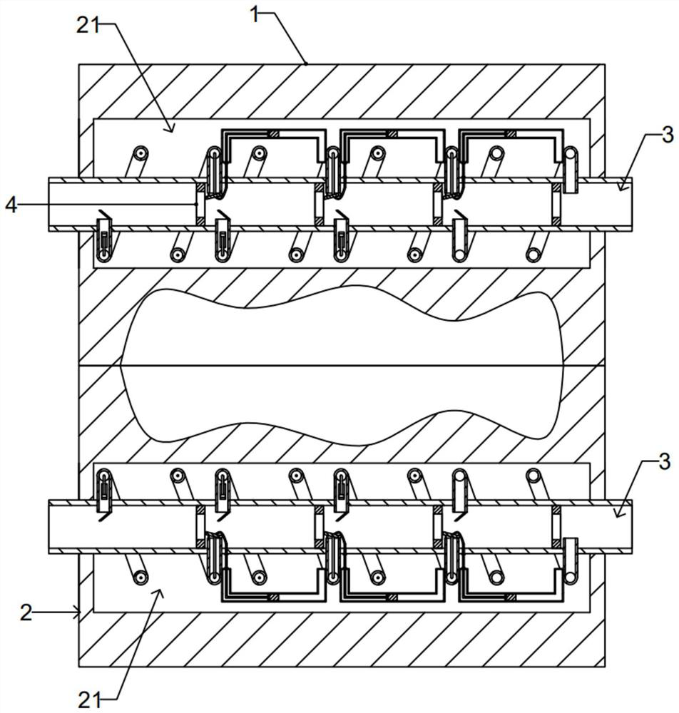
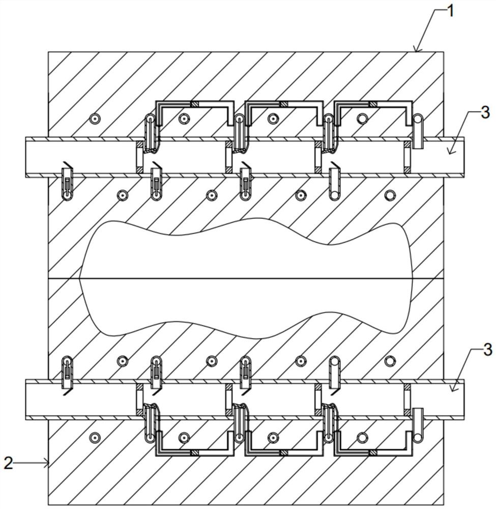
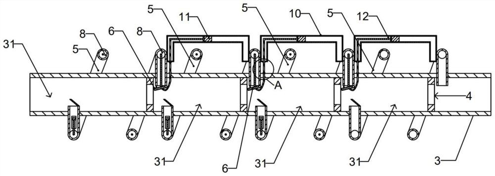
[0037] A rapid cooling injection mold includes a first mold 1 and a second mold 2 that are engaged with each other. The first mold 1 and the second mold 2 are engaged with each other to form a sealed cavity, and the injection molded product is cooled after being heated in the sealed cavity. The first mold 1 and the second mold 2 are provided with cooling pipes 3, and the cooling liquid flows through the cooling pipes 3 to cool the cooling pipes 3, and then the injection molded products are cooled through the cooling pipes 3, and several cooling pipes are arranged at intervals in the cooling pipes 3. part 4, and the cooling part 4 divides the cooling pipe 3 into several connected cooling sections 31, the cooling liquid flows in the cooling pipe 3, and when the cooling liquid flows through the cooling part 4, the cooling part 4 performs secondary cooling on the cooling liquid and absorbs The heat of the cooling liquid keeps the cooling liquid at a lower cooling temperature during...

Embodiment 2

[0048] The difference between the second embodiment and the first embodiment is that the cooling pipeline 3 and the spiral heat exchange tube 5 are embedded in the first mold 1 and the second mold 2, and the cooling pipeline 3 and the spiral heat exchange tube 5 are set in an embedded manner. The cooling pipe 3 and the spiral heat exchange tube 5 are directly in contact with the mold to improve the cooling efficiency of the mold.

[0049] An injection molding system includes a main body of the injection molding system and the above-mentioned rapidly cooling injection mold.

[0050] Working principle: The cooling liquid flows through the cooling pipe 3. When the cooling liquid flows through the cooling part 4, the cooling part 4 performs secondary cooling on the cooling liquid and absorbs the heat of the cooling liquid, so that the cooling liquid keeps flowing in the cooling pipe 3. lower cooling temperature;

[0051] When the temperature of the liquid outlet of the spiral hea...


PUM


Abstract

The injection mold comprises a first mold body and a second mold body, a plurality of cooling pieces are arranged in a cooling pipeline at intervals, and the liquid inlet end, stretching into a cooling section, of a spiral heat exchange pipe is fixedly connected with a first liquid guide plate; the spiral heat exchange pipe extends into the liquid outlet end of the next adjacent cooling section and is rotationally connected with a second liquid guide plate, the water pressing unit comprises a liquid pressing block and a rotating wheel, a liquid pressing plate is arranged in the liquid pressing block in a sliding mode, and a first limiting plate for blocking rotating blades is fixedly connected to the flexible pull rod. Cooling liquid is secondarily cooled through the cooling piece, so that the cooling liquid is kept at a low cooling temperature in the cooling pipeline in the flowing process, and through cooperation of a temperature difference pipe, a liquid pressing block, a liquid pressing plate, a rotating wheel and other structures, the spiral heat exchange pipe is subjected to countercurrent cooling, and vaporific cooling liquid with high impact force and low pressure is generated; and emphasized cooling of too many accumulated parts of injection molding products is achieved.

Description

technical field [0001] The invention relates to the technical field of injection molds, in particular to a rapidly cooling injection mold and an injection molding system thereof. Background technique [0002] Injection molded parts usually use injection molds for injection molding. The structure of the mold generally has two modules, the upper mold and the lower mold are sealed and combined to form an injection cavity in the middle. Because molten plastic particles are added during pouring, it is easy to make the mold core, mold, etc. The structure is deformed, so it is necessary to accelerate the cooling after pouring and make the injection molded parts form faster. There are also some cooling systems at present, which are to set some through holes inside the mold, and then inject water into the through holes to make it cool, but the cooling effect of this structure is relatively slow, and the cooling water in the through holes needs to be constantly replaced. [0003] In ...

Claims


Application Information

Patent Timeline
IPC IPC(8): B29C45/73B29C45/26B29C45/78
Inventor 韩磊
Owner 江苏通工金属科技有限公司
Learn More