

Automatic feeding device for mandrels
An automatic feeding and mandrel technology, applied in conveyor control devices, transportation and packaging, conveyor objects, etc., can solve the problems of low production efficiency, long mandrel time, high labor cost, and increase the number of placements. Effect
- Summary
- Abstract
- Description
- Claims
- Application Information
AI Technical Summary
Problems solved by technology
Method used
Image

Examples
Embodiment 1
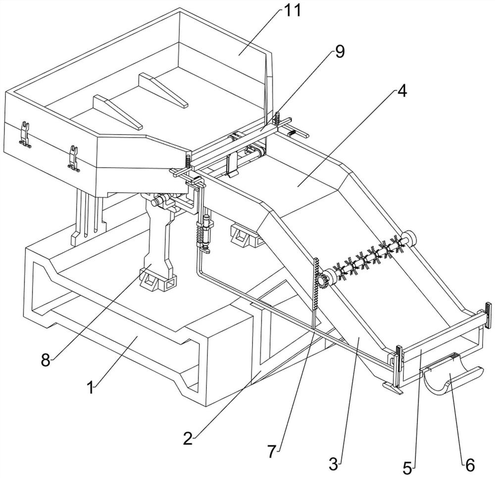
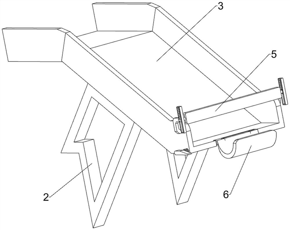
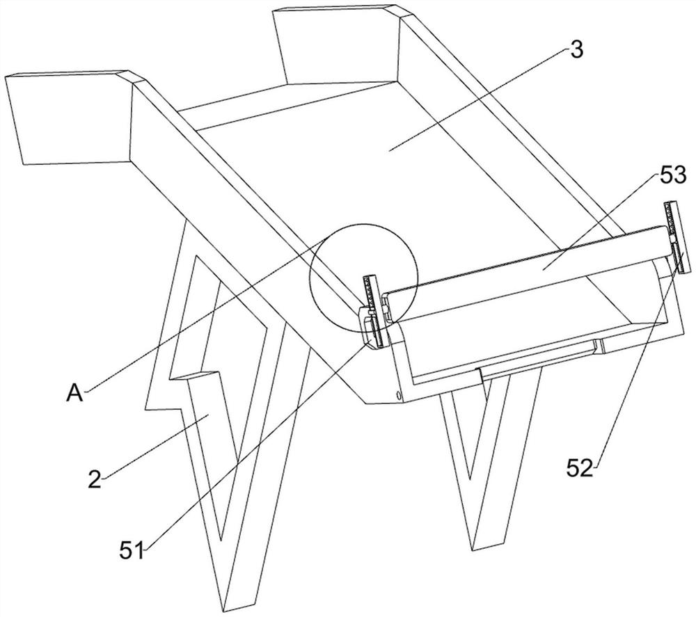
[0036] A kind of mandrel automatic feeding device, such as Figure 1 to Figure 5 As shown, it includes a mounting table 1, a mounting frame 2, a guide plate 3, a transmission plate 4, a discharging mechanism 5, a feeding mechanism 6 and a pushing mechanism 7. The right side of the mounting table 1 is symmetrically provided with a mounting frame 2 front and back, and the mounting frame 2 The top is connected with a guide plate 3, the left side of the guide plate 3 is provided with a transmission plate 4, the right side of the top of the guide plate 3 is provided with a discharge mechanism 5, the discharge mechanism 5 can place the mandrel, and the right side of the guide plate 3 A feeding mechanism 6 is provided, which can drive the mandrels to load materials sequentially. The transmission plate 4 is provided with a pushing mechanism 7, which can drive the discharging mechanism 5 and the feeding mechanism 6 to operate automatically.
[0037] The discharge mechanism 5 includes a...
Embodiment 2
[0041] On the basis of Example 1, such as figure 1 , Image 6 , Figure 7 , Figure 8 , Figure 9 , Figure 10 , Figure 11 , Figure 12 with Figure 13 As shown, the pushing mechanism 7 includes a first mounting rod 71, a second mounting rod 72, an electric push rod 73, a special-shaped rod 74, a second spring 75, a pressing rod 76, a bearing seat 77, a rack 78, a pushing rod 79 and Gear 711, the bottom left front side of the transmission plate 4 is provided with a first installation rod 71, the front side of the lower part of the first installation rod 71 is slidingly provided with a special-shaped rod 74, and a second spring 75 is connected between the special-shaped rod 74 and the first installation rod 71 , the right side of the first installation rod 71 is provided with a second installation rod 72, the second installation rod 72 is provided with an electric push rod 73, the telescopic rod of the electric push rod 73 is against the special-shaped rod 74, and the r...
Embodiment 3
[0046] On the basis of Example 2, such as figure 1 , Figure 14 with Figure 15 As shown, it also includes an expansion mechanism 11, the expansion mechanism 11 can expand the number of mandrels placed, the expansion mechanism 11 includes a clamping rod 111, a clamping plate 112 and a clamping frame 113, a clamping frame 113 is placed on the top of the screening frame 84, and the clamping frame 113 Both front and rear sides are symmetrically provided with clamping plates 112 , and both sides of the screening frame 84 are symmetrically provided with clamping rods 111 , and the clamping plates 112 can be inserted on the clamping rods 111 .
[0047] Align the clamping plate 112 on the clamping frame 113 with the clamping rod 111 and insert it, so that the clamping frame 113 can be fixed on the screening frame 84, thereby increasing the number of mandrels placed.
PUM
 Abstract
Description
Claims
Application Information