Railway vehicle control relay panel

A technology for controlling relays and rail vehicles. It is used in locomotives, substations/switchgear boards/panels/desks, etc. It can solve problems such as non-compliance with industrial electrical equipment requirements, electrical system failures, and easy deformation of sub-boards, and achieve enhanced strength. , the effect of increasing the strength and increasing the number of layouts

Active Publication Date: 2015-05-06
CRRC QINGDAO SIFANG CO LTD
View PDF9 Cites 3 Cited by
  • Summary
  • Abstract
  • Description
  • Claims
  • Application Information

AI Technical Summary

Problems solved by technology

[0003] This type of control relay panel pressure plate structure has certain disadvantages. The pressure plate structure and sub-board are easy to deform, which can easily lead to loosening of the sub-board, resulting in electrical system failure, which does not meet the requirements of industrial electrical equipment.

Method used


Image

  • Railway vehicle control relay panel
  • Railway vehicle control relay panel
  • Railway vehicle control relay panel

Examples


Embodiment 1

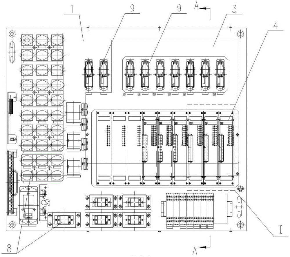
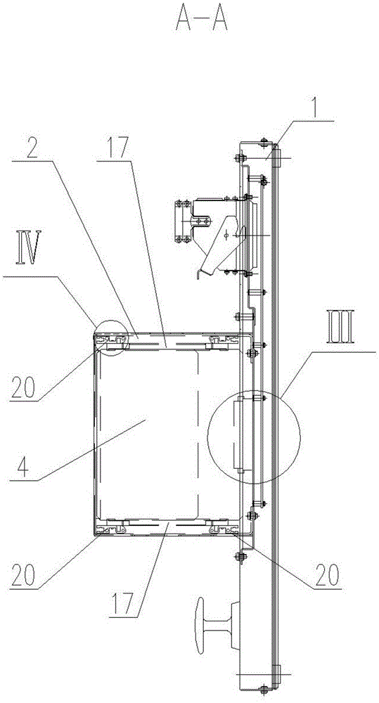
[0031] like Figure 1 to Figure 6 As shown, a rail vehicle control relay panel includes a main frame. The main frame includes a panel mounting frame 1 and a sub-board mounting frame 2 . The sub-board mounting frame 2 protrudes from the panel mounting frame 1 .

[0032] The panel installation framework 1 includes a square box body, the bottom surface of which is a detachable bottom plate, the motherboard 3 is bolted into the square box body, and the bottom plate is provided to facilitate the installation and disassembly of the motherboard 3 .

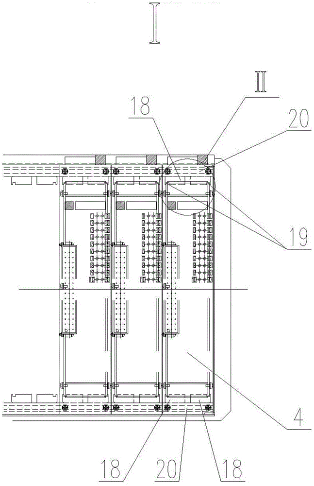
[0033] A sub-board installation framework 2 is arranged on one side of the square box body. The sub-board installation framework 2 protrudes from the panel installation framework 1 and is perpendicular to it. The sub-board installation framework 2 includes a cuboid frame, and the cuboid frame and the panel installation framework 1 are integrated. , multiple groups of chute assemblies 17 for inserting the sub-board assembly 4 are arranged...

Embodiment 2

[0047] like Figure 10 As shown, the difference between this embodiment and Embodiment 1 is that a plurality of first connectors 9 are also provided on the panel mounting frame 1 , and some sub-board assemblies 4 in multiple groups of sub-board assemblies 4 pass through third connectors 11 It is electrically connected with the motherboard 3 and outputted through the first connector 9 of the motherboard 3 , and the other sub-board components 4 are electrically connected with the first connector 9 on the panel mounting frame 1 through wires 12 . Sufficient length is reserved for the wire 12, and the wire can be connected to the sub-board assembly 4 smoothly and conveniently after the sub-board assembly 4 is removed.

[0048] Since the motherboard 3 is a printed circuit board, its routing is fixed, so electrical components such as relays 8 that are determined to be used or not changed (general) are arranged on the sub-board assembly 4 connected to the motherboard 3, according to ...


PUM


Abstract

The invention relates to a railway vehicle control relay panel which comprises a main body framework, and primary panel assemblies and secondary panel assemblies which are arranged in the main body framework, wherein the main body framework comprises a panel surface mounting framework and a secondary panel mounting framework which protrudes out of the panel surface mounting framework; primary panels are arranged in the panel surface mounting framework; multiple groups of secondary panel assemblies perpendicular to the primary panels are arranged in parallel in the secondary panel mounting framework; the secondary panel assemblies and the primary panels are in circuit connection; and multiple first connectors used for outputting to the outside are arranged on the primary panels. According to the mounting structures of the secondary panels, the mounting strength is improved, the wiring space is widened, the arrangement number of relays is increased, the looseness faults of the secondary panels are reduced, the secondary panels are of double-plate structures, the double plates are enhanced by each other, and the strength of the secondary panels is improved.

Description

technical field [0001] The invention relates to a relay panel, in particular to a rail vehicle control relay panel. Background technique [0002] The control relay boards for various types of CRH2 EMUs adopt the structure of the main board and the sub-board. Both the main board and the sub-board are wired with circuit boards. The sub-board is arranged with components such as relays and diodes. The sub-board and the main board are connected by connectors The sub-board adopts a pressing plate structure to press each sub-board uniformly on the frame of the control relay panel. Time relays and other components are arranged on the control relay board. The wiring of the components on the board and the wiring of the main board are connected through the connector on the board. The connector is the external electrical interface of the control relay board. [0003] This type of control relay panel pressure plate structure has certain disadvantages. The pressure plate structure and su...

Claims


Application Information

Patent Timeline
Patent Type & Authority Applications(China)
IPC IPC(8): B61C17/00
CPCB61C17/00H02B1/04
Inventor 王洪波秦永贞陶林王克肖焦京海王利
Owner CRRC QINGDAO SIFANG CO LTD
Why Eureka
Try Eureka