Six-main-beam cutterhead center hob mounting structure and six-main-beam cutterhead

A technology for installing structures and hobs, which is applied in mining equipment, earthwork drilling, tunnels, etc., can solve the problems of low excavation efficiency, small bearing capacity of shield cutter heads, and tool wear, so as to improve excavation efficiency and excavation capacity, Enhance the effect of rock-breaking ability and bearing capacity, bearing capacity and rock-breaking ability

Pending Publication Date: 2020-09-15
中铁工程装备集团盾构制造有限公司
View PDF0 Cites 3 Cited by
  • Summary
  • Abstract
  • Description
  • Claims
  • Application Information

AI Technical Summary

Problems solved by technology

High-strength hard rock stratum is a stratum that is difficult to excavate. When the cutterhead is digging into this stratum, the following problems are likely to occur: First, the cutter of the shield cutterhead is severely worn, prone to abnormal damage, and even tool drop Therefore, the replacement frequency of the cutter is relatively high; second, the rock-breaking ability of the shield cutter head is poor, and the structural parts of the cutter head are stressed, which is prone to defects such as cracks; third, the strength of the cutter arrangement is low, resulting in The bearing capacity is small and the excavation efficiency is low
[0003] Aiming at the problems of the existing six-beam cutter head, such as serious tool wear, difficult replacement, low rock-breaking capacity, and small bearing capacity, it is urgent to design a new type of cutter head to solve the aforementioned technical problems

Method used


Image

  • Six-main-beam cutterhead center hob mounting structure and six-main-beam cutterhead
  • Six-main-beam cutterhead center hob mounting structure and six-main-beam cutterhead
  • Six-main-beam cutterhead center hob mounting structure and six-main-beam cutterhead

Examples


Embodiment Construction

[0032] The installation structure of the center hob of the six main beam cutterheads and the six main beam cutterheads of the present invention will be described in more detail below in conjunction with the accompanying drawings and through specific implementation methods.

[0033] In describing the present invention, it is to be understood that the terms "upper", "lower", "front", "rear", "left", "right", "top", "bottom", "inner", " The orientation or positional relationship indicated by "outside", etc. is based on the orientation or positional relationship shown in the drawings, and is only for the convenience of describing the present invention and simplifying the description, rather than indicating or implying that the referred device or element must have a specific orientation, so as to Specific orientation configurations and operations, therefore, are not to be construed as limitations on the invention.

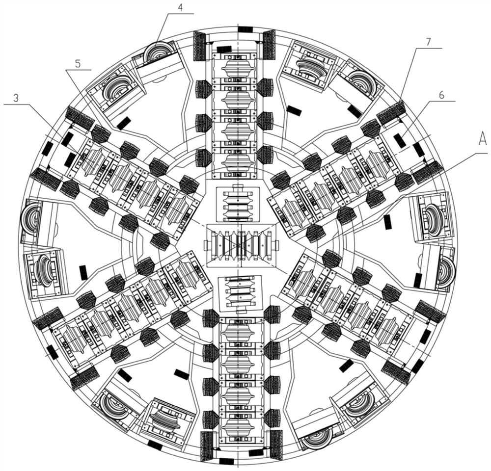
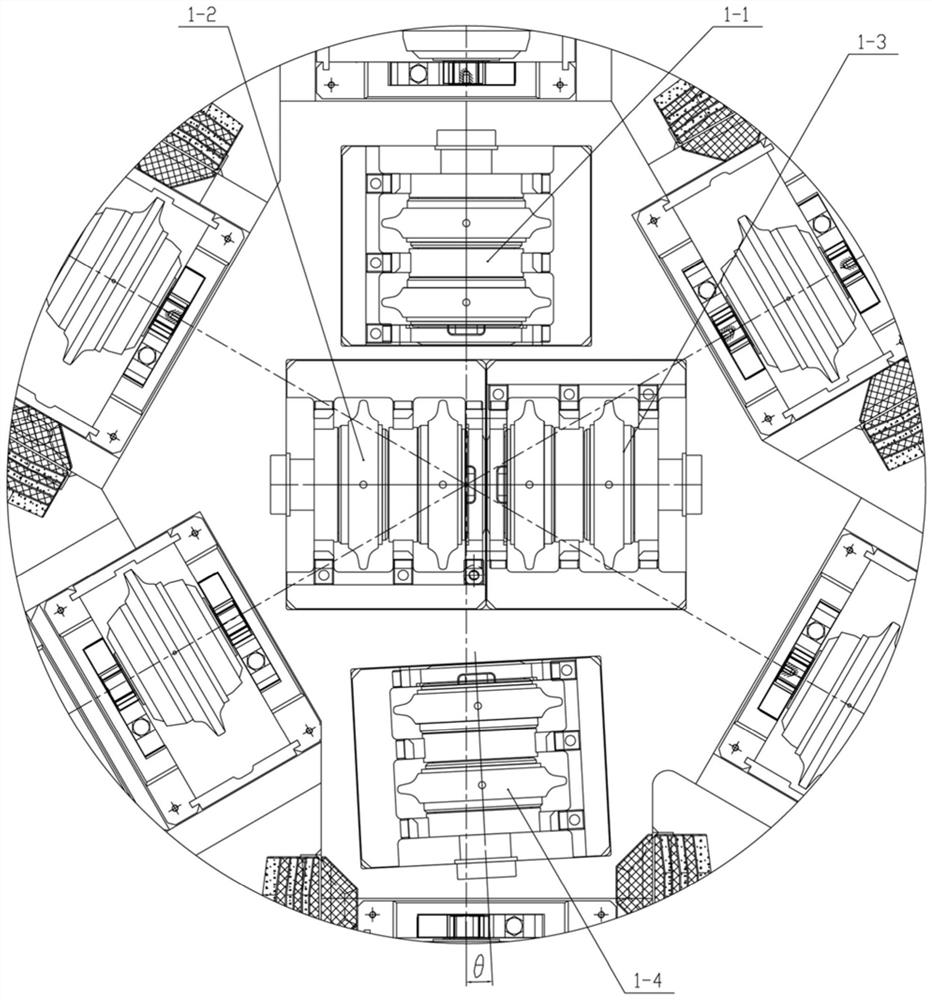
[0034] see Figure 1-Figure 11 , this embodiment discloses a cent...


PUM


Abstract

The invention relates to the technical field of engineering equipment special for tunnels, in particular to a six-main-beam cutterhead center hob mounting structure. The six-main-beam cutterhead center hob mounting structure comprises a cutterhead, a center hob set is arranged in the center of the front end face of the cutterhead, the center hob set comprises a first hob module, a second hob module, a third hob module and a fourth hob module, the four hob modules are in a cross shape, the hob axis of the fourth hob module deflects towards one side by an angle theta to provide arrangement spacefor a front face hob set, the arrangement number of front face hobs is increased, the hob size of the front hob set is larger than the hob size of the center hob set; and a six-main-beam cutterhead comprises the six-main-beam cutterhead center hob mounting structure. According to the six-main-beam cutterhead center hob mounting structure, the arrangement number of the front face hobs can be increased, and due to the fact that the front face hobs are larger in size and higher in bearing capacity and rock breaking capacity, the rock breaking capacity and the bearing capacity of a center area ofthe cutterhead are enhanced, and then the tunneling efficiency and the tunneling capacity of the cutterhead are improved.

Description

technical field [0001] The invention relates to the technical field of special engineering equipment for tunnels, in particular to a center hob installation structure of six main beam cutter heads and six main beam cutter heads. Background technique [0002] In the field of underground engineering, the application of shield tunneling method is more and more widely, especially in the construction of subway tunnels, the advantages of shield tunneling method construction are particularly significant. The cutter head is one of the key components on the shield machine, and it directly undertakes the task of excavating the tunnel face. High-strength hard rock stratum is a stratum that is difficult to excavate. When the cutterhead is digging into this stratum, the following problems are likely to occur: First, the cutter of the shield cutterhead is severely worn, prone to abnormal damage, and even tool drop Therefore, the replacement frequency of the cutter is relatively high; sec...

Claims


Application Information

Patent Timeline
Patent Type & Authority Applications(China)
IPC IPC(8): E21D9/08
CPCE21D9/08
Inventor 张家年王国政李凯凯师清豪胡玉娟李刚
Owner 中铁工程装备集团盾构制造有限公司
Why Eureka
Try Eureka