A pipe jacking machine and a returnable pipe jacking construction method

A technology of pipe jacking machine and inner shell, which is applied in the direction of pipe/pipe joint/pipe fitting, mechanical equipment, pipe laying and maintenance, etc. It can solve the problems of high working intensity, limitation of cutting area of ​​cutterhead, and influence of tunneling efficiency, etc., and achieves improvement The effect of driving efficiency and increasing the cutting area

Pending Publication Date: 2018-11-27
CHINA RAILWAY CONSTR HEAVY IND
View PDF10 Cites 18 Cited by
  • Summary
  • Abstract
  • Description
  • Claims
  • Application Information

AI Technical Summary

Problems solved by technology

[0005] However, on the one hand, because the cutting surface of the cutterhead is affected by the inner cavity of the shell, the cutting area of ​​the cutterhead is limited, thereby affecting the improvement of tunneling efficiency; Manually dismantling the connecting parts between the outer shell and the inner shell, the work intensity is high, which makes it inconvenient for the pipe jacking machine to roll back, which is not conducive to automatic rollback
[0006] Therefore, the existing pipe jacking machine is not only not conducive to improving the excavation efficiency, but also not conducive to the realization of automatic retraction

Method used


Image

  • A pipe jacking machine and a returnable pipe jacking construction method
  • A pipe jacking machine and a returnable pipe jacking construction method
  • A pipe jacking machine and a returnable pipe jacking construction method

Examples


Embodiment Construction

[0052] The following will clearly and completely describe the technical solutions in the embodiments of the present invention with reference to the accompanying drawings in the embodiments of the present invention. Obviously, the described embodiments are only some, not all, embodiments of the present invention. Based on the embodiments of the present invention, all other embodiments obtained by persons of ordinary skill in the art without making creative efforts belong to the protection scope of the present invention.

[0053] In order to enable those skilled in the art to better understand the solution of the present invention, the present invention will be further described in detail below in conjunction with the accompanying drawings and specific embodiments.

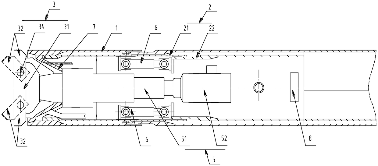
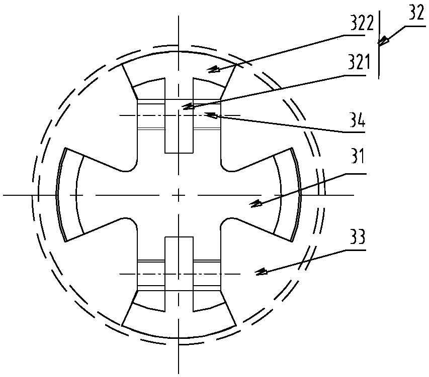
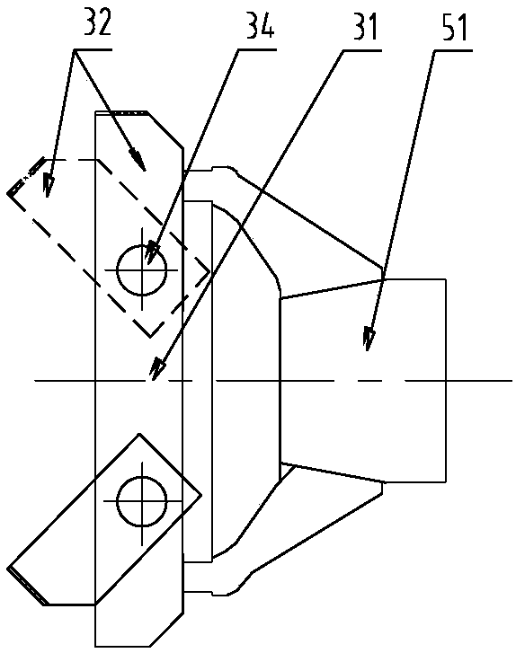
[0054] Please refer to Figure 1 to Figure 4 , figure 1 A structural schematic diagram of a pipe jacking machine provided for a specific embodiment of the present invention; figure 2 for figure 1 The front view ...


PUM


Abstract

A pipe jacking machine includes a cutter head fixedly connected to the inner housing and capable of entering the central cavity, and a folding cutter holder having a first end hinged to the cutter head and a second end foldable about the first end into the central cavity. The cutter head includes an outer housing and an inner housing, and a cutter assembly and a retractor fixedly connected to theinner housing at an end remote from the cutter assembly. The cutting area of the folding cutter holder is free from the influence of the shell, and can avoid manual overturning, which is favorable forimproving the tunneling efficiency and realizing automatic retraction. In addition, the inner shell is dragged by the back dragging device so that the inner shell drives the cutter assembly to be dragged from the central cavity of the outer shell into the originating well, thereby avoiding manual disassembly of the connection between the outer shell and the inner shell and facilitating further automatic retraction. Therefore, the pipe jacking machine provided by the invention is not only conducive to improving the tunneling efficiency, but also conducive to realizing automatic retraction. Theinvention also discloses a returnable pipe jacking construction method applied to the pipe jacking machine as described above.

Description

technical field [0001] The invention relates to the technical field of engineering equipment, in particular to a pipe jacking machine. The invention also relates to a retractable pipe jacking construction method. Background technique [0002] On the one hand, the development of underground space has gradually become necessary due to environmental damage, traffic congestion, and large land occupation caused by the rapid urban development; Serious impacts on life and ground transportation have drawn increasing attention to civilized construction. Naturally, the construction of pipe jacking machines has been widely used in tunnel excavation, municipal drainage, communication cables, gas pipelines, power cables and other fields due to its advantages such as small impact on the construction surroundings, construction through obstacles, wide range of adaptability to soil quality, and strong crushing capacity. . [0003] A pipe jacking machine usually includes a cutter head, a c...

Claims


Application Information

Patent Timeline
Patent Type & Authority Applications(China)
IPC IPC(8): F16L1/028
CPCF16L1/028
Inventor 程永亮彭正阳刘学申鹏飞张瑞临马龙明刘任丰陈庆宾张卫东
Owner CHINA RAILWAY CONSTR HEAVY IND
Why Eureka
Try Eureka