Eureka AIR delivers breakthrough ideas for toughest innovation challenges, trusted by R&D personnel around the world.

Laser template cutting machine

A laser template and cutting machine technology, applied in laser welding equipment, welding/cutting auxiliary equipment, auxiliary devices, etc., can solve the problems of inability to complete, large size, large platform, etc., and achieve short operation time, high production efficiency, and operation. easy effect

Inactive Publication Date: 2016-03-16
苏州市众鑫激光科技有限公司
View PDF6 Cites 4 Cited by
  • Summary
  • Abstract
  • Description
  • Claims
  • Application Information

AI Technical Summary

Problems solved by technology

Since the laser head is fixed and the template is moved, the required platform is large and the equipment is heavy
Especially for the cutting of large templates, due to the large size, it is generally impossible to complete

Method used


Image

  • Laser template cutting machine
  • Laser template cutting machine
  • Laser template cutting machine

Examples


Embodiment Construction

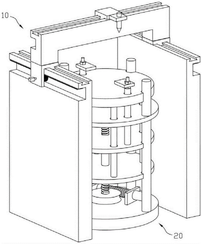
[0039] Such as figure 1 , a laser template cutting machine, including a cutting mechanism 10 and a template clamp 20.

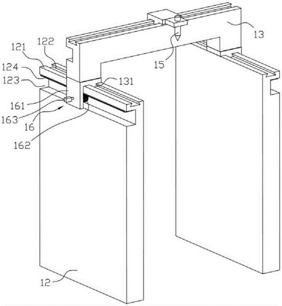
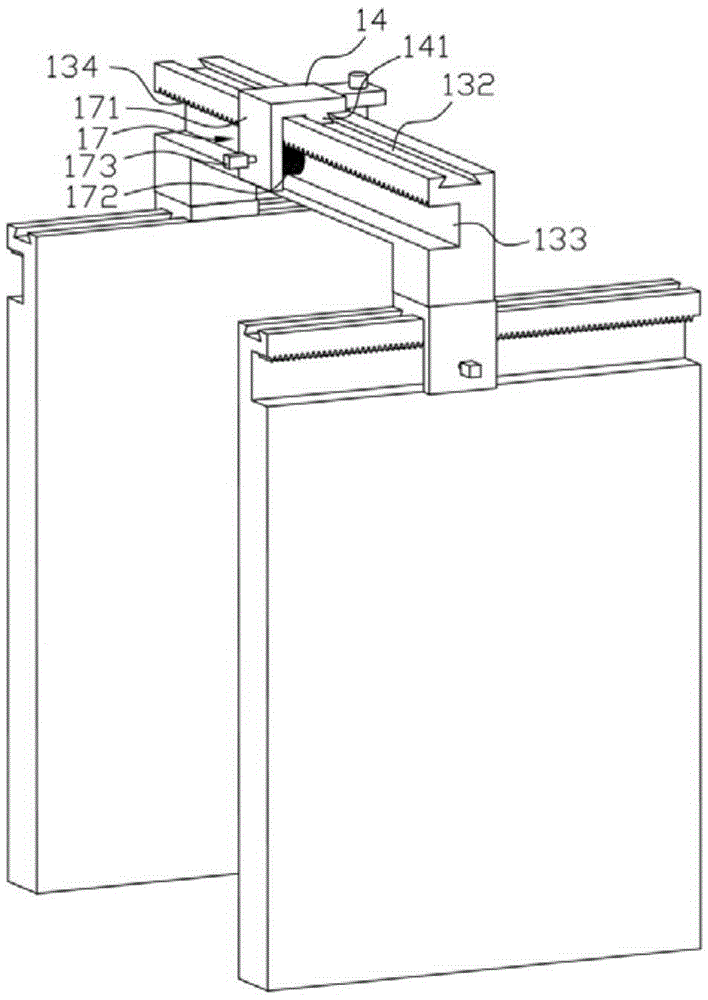
[0040] combine figure 2 , image 3 , the cutting mechanism 10 includes a pair of frame plates 12 arranged left and right, a beam 13 spanning a pair of frame plates, a laser frame 14 installed on the beam, a laser head 15 installed on the laser frame; the pair A Y-direction slideway is provided on the frame plate, and an X-direction slideway is provided on the beam. On the X-direction slideway of the beam; the laser head is connected with the laser generator through the reflection device.

[0041] In the above-mentioned cutting mechanism 10, the pair of frame plates 12 includes a left frame plate and a right frame plate, the first Y-direction slideway 121 is provided on the left frame plate, and the first Y direction slideway 121 is provided on the right frame plate. Two Y-direction slideways; a first Y-direction chute 122 with a trapezoidal cross-section...


PUM


Abstract

The invention discloses a laser template cutting machine which comprises a cutting mechanism and a template fixture, wherein the cutting mechanism comprises a laser head; the laser head performs two-dimensional motion through an X-direction slide and Y-direction slides; and the template fixture is positioned between a pair of rack plates of the cutting mechanism and is positioned below the laser head. According to the laser template cutting machine, workpieces to be cut are located through the template fixture, and templates are cut through laser beams, so that the speed is high, the efficiency is high, and the cutting is smooth, fluent and neat.

Description

Technical field: [0001] The invention relates to the technical field of laser templates, in particular to a laser template cutting machine. Background technique: [0002] Stencils, especially large stencils, are widely used in a wide range of applications. Electricity, heat, or knife cutting are generally used for cutting. With the wide application of lasers, laser cutting is gradually being used in the field of stencil cutting due to its high speed and high efficiency. The principle is that under the action of a high-voltage electric field, the electrons in the discharge tube move and collide with the gas to generate photoelectrons, which are accelerated through a long distance to form a laser beam with a wavelength of 10.64um to be emitted to cut the template. The laser cutting machine currently used is mainly composed of a mobile platform and a laser head. The template is placed on the mobile platform, and the laser head completes the cutting as the mobile platform moves....

Claims


Application Information

Patent Timeline
Patent Type & Authority Applications(China)
IPC IPC(8): B23K26/38B23K26/70B23K37/04
CPCB23K26/38B23K37/04
Inventor 高扬
Owner 苏州市众鑫激光科技有限公司
Why Eureka
Eureka Blog
Learn More