Coal mining excavation saw

A tunnel sawing and sawing technology, which is applied in the field of cutting machinery, can solve the problems of the tunnel shearer being bulky, unable to cut the rear section, and the use space is relatively limited, so as to improve the use value and economy. Value, good for cooling and chip evacuation, easy to transport and store

Inactive Publication Date: 2012-10-24
刘素华
View PDF7 Cites 4 Cited by
  • Summary
  • Abstract
  • Description
  • Claims
  • Application Information

AI Technical Summary

Problems solved by technology

The blasting method is highly dangerous and prone to accidents, and the coal produced is too pulverized and the lump coal rate is low
The driving type coal mining machine is bulky and has great restrictions on the use of space
With the development of technology, higher requirements are put forward for the production of briquettes, but the above coal mining methods are not applicable, and cannot meet the needs of mining briquettes in this section of coal mining.
Chinese Patent Application No. 96113151.9 discloses a "chainsaw coal mining machine roadheader cutting device". Cutting, multiple cuttings are required to complete a coal mining process
When driving to cut coal, the frame used to support it will prevent the cutting area from contacting the coal seam

Method used


Image

  • Coal mining excavation saw
  • Coal mining excavation saw
  • Coal mining excavation saw

Examples


Embodiment 1

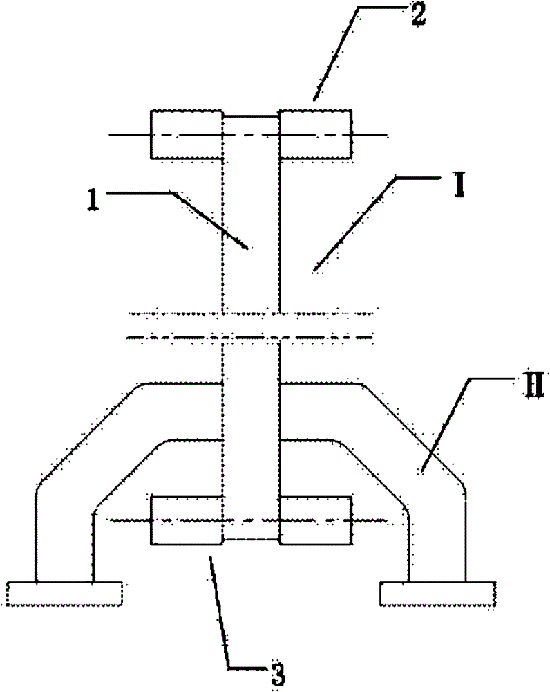
[0041] see Figure 1-Figure 16 , The tunneling saw provided by the present invention includes a machine body II and a sawing mechanism I. Saw mechanism 1 comprises driving wheel 3, driven wheel 2, saw blade 4, cooling device 12 and support frame 1. The body II includes a driving mechanism 5 connected to the driving wheel 3 . The saw blade 4 is wound around the driving wheel 3 and the driven wheel 2 in a tensioned state. A support frame 1 is arranged between the driving wheel 3 and the driven wheel 2, the front end of the support frame 1 is arranged between the two driven wheels 2, and the shaft of the support frame 1 is movably connected with the driven wheel 2. The cooling spray head of the cooling device 12 is arranged on the supporting frame 1 between the two wheels of the driven wheel 2. The part composed of the driving wheel 3, the driven wheel 2 and the supporting frame 1 is divided into a driving sawing part and a cutting part. The cross section of the saw blade 4 Th...

Embodiment 2

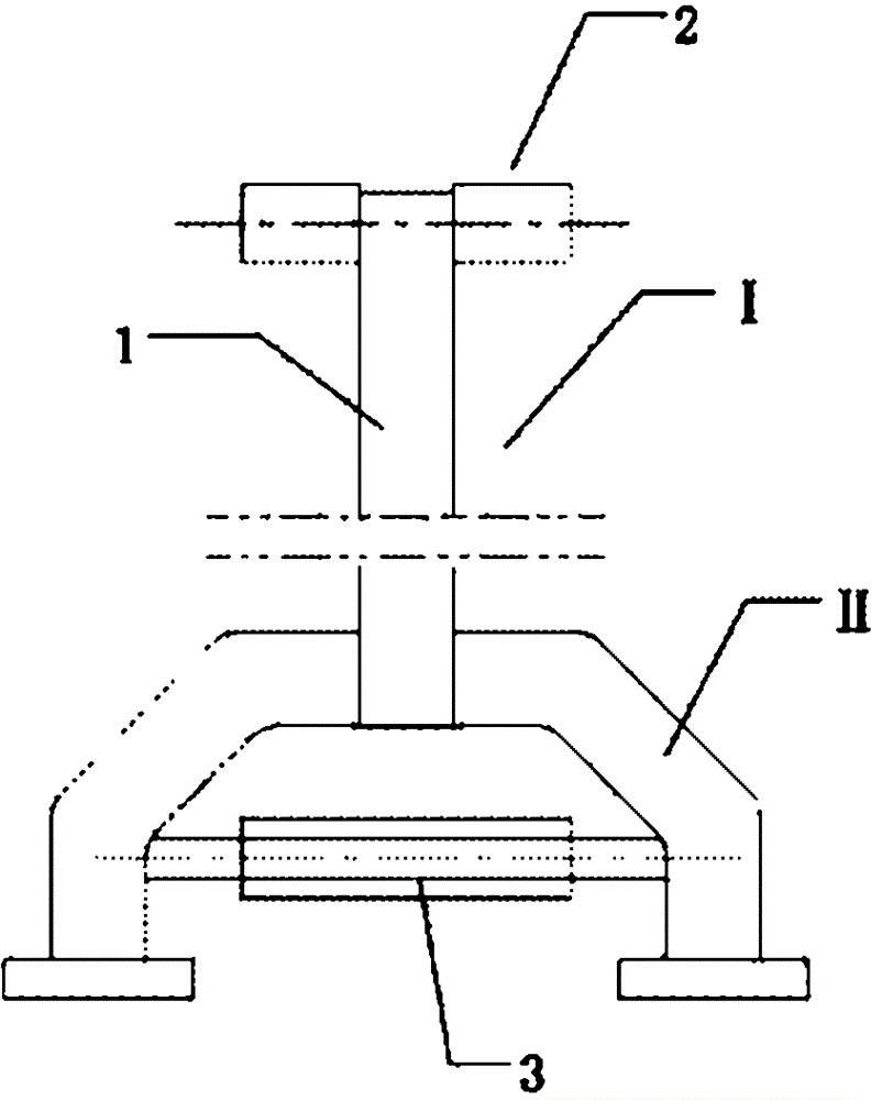
[0047] see figure 2 , except that the following changes, other with embodiment 1.

[0048] The driving wheel 3 is composed of one wheel; the driven wheel 2 is composed of two wheels arranged side by side on the same shaft, and the two wheels are distributed at both ends of the shaft. One end of the support frame 1 is connected on the axle body between the two wheels of the driven wheel 2, and the other end is connected on the body II through the connecting rod 6.

[0049] Saw blade 4 selects chain saw for use. The sawtooth material is made of titanium alloy.

[0050] During work, the output shaft 10 of the driving mechanism is connected with the driving wheel 3 to drive the driving wheel 3 to rotate, thereby driving the driven wheel 2 to rotate through the chain saw wound on the driving wheel 3 and the driven wheel 2 . The sawing of the material is achieved with power applied to the road saw. During the sawing process, the chain saw should be cooled by the cooling device ...

Embodiment 3

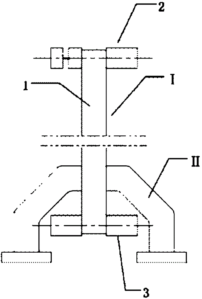
[0052] see image 3 , except that the following changes, other with embodiment 1.

[0053]The driving wheel 3 is composed of two wheels arranged side by side on the same shaft, and the two wheels are distributed at both ends of the shaft; the driven wheel 2 is composed of three wheels arranged on the same shaft, and the two wheels are arranged side by side on the at one end of the axle, and the other wheel is at the other end. One end of the support frame 1 is connected on the shaft body between two parallel wheels of the driven wheel and a wheel, and the other end is connected on the shaft body between the two wheels of the driving wheel.

[0054] Saw blade 4 selects chain saw for use. The sawtooth material is made of high-speed steel.

[0055] During work, the output shaft 10 of the drive mechanism is connected to the driving wheel 3 to drive the driving wheel 3 to rotate, thereby driving the driven wheel 2 to rotate through the chain saw wound around the driving wheel 3 ...


PUM


Abstract

The invention belongs to the field of cutting machinery, and in particular relates to a coal mining excavation saw. The invention aims to puts forward a coal mining excavation saw with deep excavating function, ability to realize a variety of cutting functions, small energy loss, long service life, and high cutting efficiency. The technical scheme is as the following: a coal mining excavation saw comprises a body and a sawing mechanism, etc. The sawing mechanism includes a driving wheel, a driven wheel, saw blades, a cooling device and a supporting frame, etc. The driven wheel is composed of at least one wheel. The saw blades are wound on the driving wheel and the driven wheel in a tensioning state, and the supporting frame is disposed between the driving wheel and the driven wheel. When there exists one driven wheel, the driven wheel is disposed on one side of the supporting frame, and when there exist a plurality of driven wheels, they are symmetrically arranged on two sides of the supporting frame. The spray nozzle of the cooling device is arranged on the supporting frame. The saw surface width is not less than the width sum of the driven wheel and the supporting frame. The excavation saw of the invention has the advantages of good excavation function, small energy loss, long service life, and multiple cutting functions, thus being able to greatly improve the mining efficiency of coal briquettes.

Description

technical field [0001] The invention belongs to the field of cutting machinery, and in particular relates to a tunneling saw for coal mining. Background technique [0002] At present, the coal mining methods of existing coal mines mostly adopt blasting method or driving type coal mining machine to carry out coal mining. The blasting method is highly dangerous and prone to accidents, and the coal produced is too pulverized and the lump coal rate is low. The driving type coal mining machine is bulky and has great restrictions on the use of space. With the development of technology, higher requirements have been put forward for the production of briquettes, but the above-mentioned coal mining methods are not applicable, and cannot meet the needs of this section of mining briquettes in coal mining. Chinese Patent Application No. 96113151.9 discloses a "chainsaw coal mining machine roadheader cutting device". Cutting, it is necessary to carry out multiple cuttings to complete ...

Claims


Application Information

Patent Timeline
Patent Type & Authority Applications(China)
IPC IPC(8): E21C25/16E21C25/18E21C35/04E21C35/22
Inventor 刘素华
Owner 刘素华
Why Eureka
Try Eureka