Propelling method for combined portion between shield tunnel segment and mine tunnel segment in subway tunnel

A technology for shield tunneling and joint parts, which is applied in tunnels, tunnel linings, underground chambers, etc., and can solve problems such as high requirements for shield propulsion deviation control, low allowable deviation error rate, and surface subsidence, so as to reduce construction risks , reduce disturbance, and greatly support the effect

Inactive Publication Date: 2014-04-09
SOUTHWEST JIAOTONG UNIV
View PDF4 Cites 19 Cited by
  • Summary
  • Abstract
  • Description
  • Claims
  • Application Information

AI Technical Summary

Problems solved by technology

This method has a high risk in construction, especially in the process of manually removing the end wall: the end wall structure supports the soil behind it, once the end wall is broken, the soil will be exposed, the mechanical balance between the stratum and the support structure will be broken, and at the same time, under the strong thrust of the shield machine, the soil will easily collapse, causing the surface to subside, and even casualties. important risk factors
[0005] After the shield machine passes through the joint, the body of the shield machine will dock with the mine tunnel section and enter the arc-shaped guide platform in the mine tunnel. At this time, the allowable deviation error rate between the shield tunneling route and the tunnel design axis is low. Existing construction methods have high requirements and difficulties for the control of shield propulsion deviation, and repeated adjustments are required. There are disadvantages such as difficult construction, long time-consuming, low efficiency, and high cost.

Method used


Image

  • Propelling method for combined portion between shield tunnel segment and mine tunnel segment in subway tunnel
  • Propelling method for combined portion between shield tunnel segment and mine tunnel segment in subway tunnel
  • Propelling method for combined portion between shield tunnel segment and mine tunnel segment in subway tunnel

Examples


Embodiment Construction

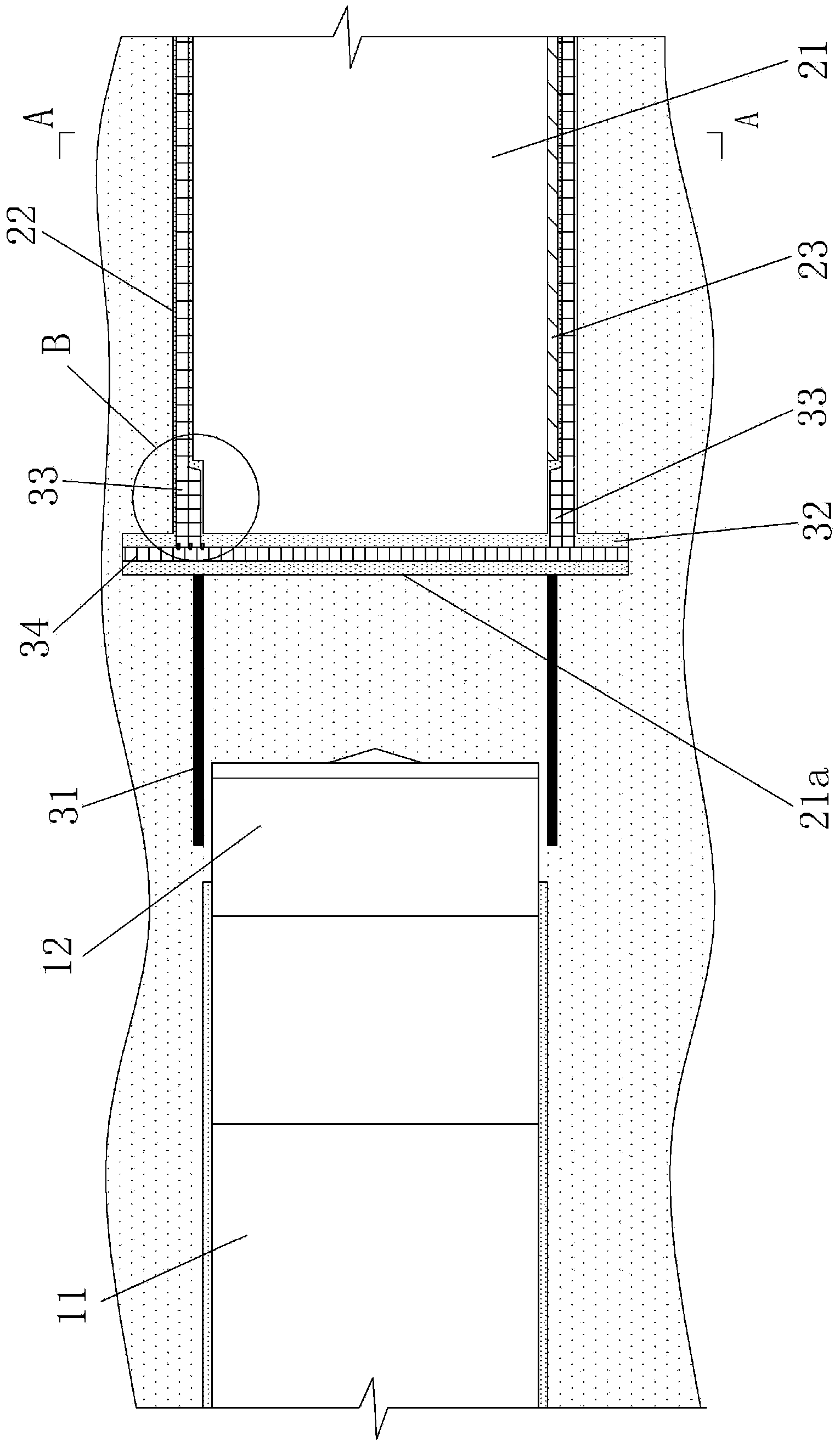
[0023] Figure 1-3 Shown, a kind of embodiment of the present invention is, a kind of advancing method of shield tunnel section and mine tunnel section joint position in a kind of subway tunnel, and its steps are:

[0024] A method for advancing the junction of a shield tunnel section and a mine tunnel section in a subway tunnel, the steps of which are:

[0025] A. The mine tunnel section 21 is constructed first, and then a circular steel sleeve 31 is horizontally driven into the surrounding rock in front of the mine tunnel section 21 face 21a, and the rear end face of the steel sleeve 31 is flush with the face 21a. Then apply grouting support to the face 21a;

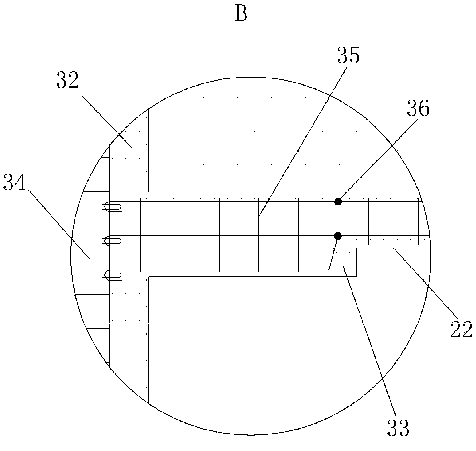
[0026] B. Closely attached to the shotcrete support and binding the glass fiber reinforcement 34 separating the end wall, and the glass fiber reinforcement 34 is bound and connected with the ring beam behind it with a steel bar 35, and the steel bar 35 for the ring beam is connected with the initial support of the min...


PUM


Abstract

Provided is a propelling method for a combined portion between a shield tunnel segment and a mine tunnel segment in a subway tunnel. The propelling method includes the first step that a steel sleeve is horizontally struck into the surrounding rock in front of a tunnel face of the mine tunnel segment after construction of the mine tunnel segment is finished, and then a shotcrete support is applied on the tunnel face; the second step that glass fiber ribs of separation end walls are bound tightly close to the shotcrete support, the glass fiber ribs and steel bars for ring beams behind the glass fiber ribs are connected in a bound mode, next the steel bars for the ring beams are connected with reserved steel bar heads of a primary support of the mine tunnel segment in a welded mode, and then the separation end walls and the ring beams are poured; the third step that an arc-shaped concrete guiding platform is poured at the bottom of the mine tunnel segment; the fourth step that when a shield tunneling machine approaches to the mine tunnel segment, the propelling speed is lowered, the shield tunneling machine is accommodated in the steel sleeve, and then the shield tunneling machine is used for directly cutting and removing the surrounding rock in the steel sleeve, the shotcrete support of the tunnel face and the separation end walls and carrying out grouting and slag removing until the shield tunneling machine passes through the ring beams and is accommodated on the arc-shaped concrete guiding platform. According to the propelling method, construction risks are low, construction is easy, efficiency is high and the cost is low.

Description

technical field [0001] The invention relates to a method for advancing the junction of a shield tunnel section and a mine tunnel section in a subway tunnel. Background technique [0002] At present, when the construction of subway tunnels encounters long-distance hard rock formations, the use of shield tunneling has disadvantages such as slow advancing speed and fast tool wear. Therefore, the mining method is often used to excavate hard rock tunnels to form a mine tunnel section, and then when the shield machine advances to the junction of the shield tunnel section and the mine tunnel section, the partition end wall is first broken to allow the shield machine to enter the mine tunnel section , to realize the connection between the shield tunnel section and the mine tunnel section. [0003] Since the mine tunnel section needs to be completed for a longer period of time before the shield tunnel section, the long-term exposure of the face of the mine tunnel section will gradua...

Claims


Application Information

Patent Timeline
Patent Type & Authority Applications(China)
IPC IPC(8): E21D11/14
Inventor 陈寿根周泽林张国亮刘继强王太平宁锐韩雪峰张恒
Owner SOUTHWEST JIAOTONG UNIV
Why Eureka
Try Eureka