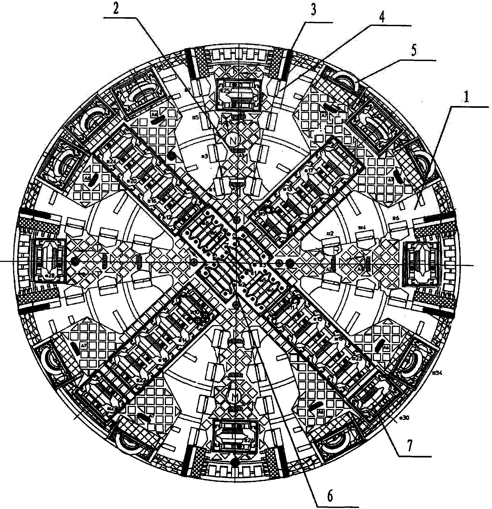
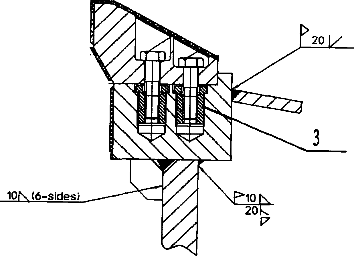
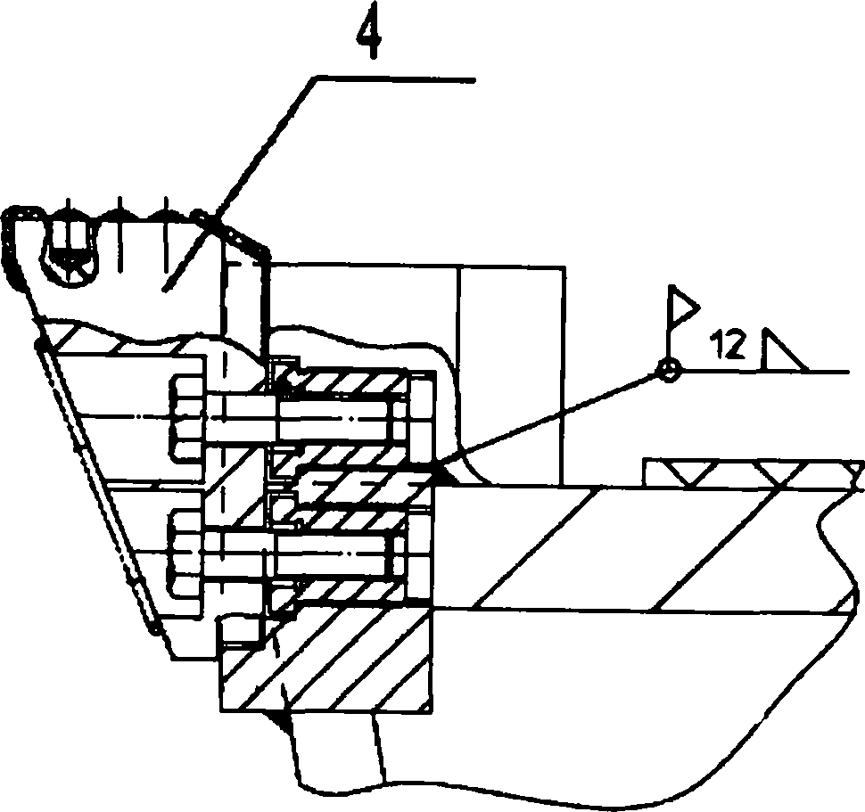
Shield cutterhead structure for uneven mutual-penetration composite rock stratum

A shield cutter head, soft and hard uneven technology, applied to mining equipment, earthwork drilling, tunnels, etc., can solve problems such as uneven distribution of strata, fracture, poor integrity, etc.

Inactive Publication Date: 2014-09-24
BEIJING URBAN CONSTR DESIGN & DEV GRP CO +1
View PDF5 Cites 19 Cited by
  • Summary
  • Abstract
  • Description
  • Claims
  • Application Information

AI Technical Summary

Problems solved by technology

Different strata or rock strata with different weathering degrees are intertwined and inter-intruded, the strata properties of the face change rapidly, the lithological characteristics are greatly different, the strata and weathering boundary transitions are frequent, the properties of the compound strata are extremely obvious, and there are thin weathered interlayers , rich in quartz and metal minerals, the stratum is broken, the integrity is poor, the rock fissures are developed, and it is easy to form massive joints. High risk, severe tool abnormal wear, high tool investment, low construction efficiency, increased construction cost and safety risks
[0005] In the uneven excavation rock surface of the uneven soft-hard inter-invasion composite rock layer, the cutting law of the hob itself of the shield machine cutter head changes. Therefore, there is a continuous problem that the hob lacks a force interface and does not turn to the eccentric grinding, and the knife ring and the knife shaft are broken by the sudden impact of the rock.
The rock strength is high, and it also contains a large amount of quartzite and metal minerals with the same high strength. The mechanical performance of the tool is extremely high, the wear of the tool is significantly increased, the life is shortened rapidly, and it also caused a large impact on the tool box and the box.
[0006] In the soft-hard inter-intruded composite rock formation, due to the uneven distribution of the face of the face, the rock is broken, and the rock is broken in blocks after cutting, and the face of the face is extremely uneven. Under the force of rock breaking, under the rotation of the cutter head of the shield machine, it is impacted by the protruding rock blocks and sharp rocks on the face of the tunnel. Caving, deformation of the bolt hole of the tool holder, thread damage
The collapsed tooth cutter, shovel cutter, broken hob cutter ring, cutter body and other remnants repeatedly stirred in front of the cutter head and in the soil bin, and could not be discharged in time, causing great impact, extrusion, and friction on the hob The hob frequently appears in a large area: it is squeezed into the knife box, causing the hob to be eccentrically worn; the knife ring is squeezed out and loses its function; the knife ring is broken or has a gap due to impact; the knife shaft is broken due to abnormal force; Extrusion with the cutter body, etc., resulting in deformation of the cutter body, extrusion of the end cover, severe extrusion and deformation of the cutter hub, and deformation of the cutter box. Finally, it cannot be removed and can only be removed by destructive gas cutting, making the cutter scrapped
The hob is stuck, and the cutter ring is severely worn. What's more, the cutter body is severely worn after the cutter ring is broken; the hob fixing wedge and bolt are deformed and broken due to indirect force.
The soft-hard inter-aggressive composite rock layer has great damage to the seal of the hob. Under long-term high pressure, the seal is damaged and fails, and water, rock debris, powder particles, etc. enter, which makes the bearing rust and wear
The front edge of the cutterhead (behind the blade holder) is wear-resistant and the main body loses protection due to the blade falling off, and the dropped blade and holder fall into the bottom of the cutterhead and are agitated by the cutterhead, causing wear

Method used


Image

  • Shield cutterhead structure for uneven mutual-penetration composite rock stratum
  • Shield cutterhead structure for uneven mutual-penetration composite rock stratum
  • Shield cutterhead structure for uneven mutual-penetration composite rock stratum

Examples


Embodiment Construction

[0030] In order to make the objectives, technical solutions and advantages of the present invention clearer, the technical solutions in the embodiments of the present invention will be described in more detail below in conjunction with the drawings in the embodiments of the present invention. In the drawings, the same or similar reference numerals denote the same or similar elements or elements having the same or similar functions throughout. The described embodiments are some, but not all, embodiments of the invention. The embodiments described below by referring to the figures are exemplary and are intended to explain the present invention and should not be construed as limiting the present invention. Based on the embodiments of the present invention, all other embodiments obtained by persons of ordinary skill in the art without creative efforts fall within the protection scope of the present invention. Embodiments of the present invention will be described in detail below ...


PUM


Abstract

The invention discloses a shield cutterhead structure for an uneven mutual-penetration composite rock stratum. The shield cutterhead structure for the uneven mutual-penetration composite rock stratum comprises a heavy cutterhead, double-edge central hobbing cutters, a single-edge front-side hobbing cutter, a single-edge circumferential hobbing cutter and an auxiliary cutter, wherein the heavy cutterhead is of a radial-plate intermediate supporting structure, and the opening rate of the heavy cutterhead ranges from 20 to 30 percent; the double-edge central hobbing cutters are vertical to each other and arranged on the central position of the heavy cutterhead; the single-edge front-side hobbing cutter is arranged above four main spiders of the heavy cutterhead according to a cutting path of the shield cutterhead; the single-edge circumferential hobbing cutter is arranged on the end part of the four main spiders according to the cutting path of the shield cutterhead; the auxiliary cutter is arranged above the spiders of the heavy cutterhread according to the cutting path of the shield cutterhead. The cutterhead structure is suitable for shield tunneling of the composite stratum which is non-uniform in hardness and mutually penetrated by each other.

Description

technical field [0001] The invention relates to the field of shield machine cutterheads, in particular to a shield cutterhead structure for soft-hard heterogeneous inter-invasion composite rock formations. Background technique [0002] Diabase has high strength and high content of quartz and metal minerals. The saturated uniaxial compressive strength of moderately weathered diabase is as high as 140MPa. At 60MPa, it belongs to hard rock; according to "Code for Geotechnical Engineering Investigation of Underground Railway and Light Rail Transit" (GB50307-1999) and "Code for Design of Railway Tunnel" (TB10003-2005), diabase belongs to extremely hard rock, and diabase with a weaker degree of weathering Greenstone, according to the actual uniaxial compressive strength, has a Platts hardness coefficient f>16, belongs to Pujian XIII category, and belongs to extremely difficult to drill formations. [0003] Medium, strong and fully weathered slate, with saturated uniaxial compr...

Claims


Application Information

Patent Timeline
Patent Type & Authority Applications(China)
IPC IPC(8): E21D9/08
Inventor 周刘刚杨凯王良郭全国恽军朱伟武福美
Owner BEIJING URBAN CONSTR DESIGN & DEV GRP CO
Why Eureka
Try Eureka