Honeycomb-shaped heat radiator of LED lamp fitting

A technology of LED lamps and heat sinks, which is applied to the cooling/heating devices of lighting devices, lighting devices, components of lighting devices, etc. Heat dissipation effect, the effect of increasing the number of placements

Inactive Publication Date: 2010-09-29
江苏尚恩光电科技有限公司
View PDF6 Cites 3 Cited by
  • Summary
  • Abstract
  • Description
  • Claims
  • Application Information

AI Technical Summary

Problems solved by technology

At present, LED integrated light sources in the industry can only achieve less than 200W due to heat dissipation problems. Even if there are related high-power LED integrated light sources, the service life of the products is low due to poor heat dissipation effects, and the market competitiveness is not strong.
Therefore, in the prior art, there is no technical inspiration to solve the heat dissipation problem of high-power LED lighting fixtures above 500W through a good honeycomb heat sink, and in practical applications, there is indeed a market for high-power LED lighting honeycomb heat sinks. need
[0005] In addition, current radiators are generally made into round or oval shapes. As a mature technology, this kind of radiator is widely circulated in processing and supply channels, but this style of radiator is very important for improving the heat dissipation per unit volume. effect, not optimal

Method used


Image

  • Honeycomb-shaped heat radiator of LED lamp fitting
  • Honeycomb-shaped heat radiator of LED lamp fitting
  • Honeycomb-shaped heat radiator of LED lamp fitting

Examples


Embodiment 1

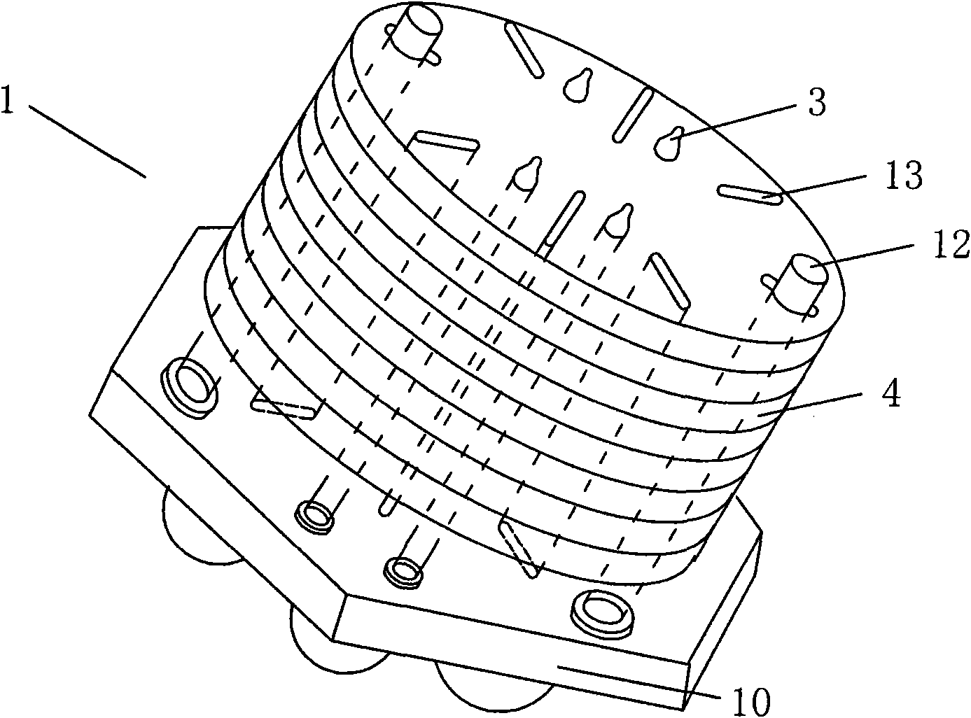
[0024] Such as Figure 1a and Figure 2a As shown, the LED lamp of the present invention includes a lampshade (not shown), an LED lighting device arranged in the lampshade, and a honeycomb heat sink 1 in contact with the LED lighting device, in order to prevent dust, insects, etc. from affecting the LED lighting device To extend the service life, the LED lighting device can be accommodated in the lampshade, which is usually made of transparent plastic, glass or other materials.

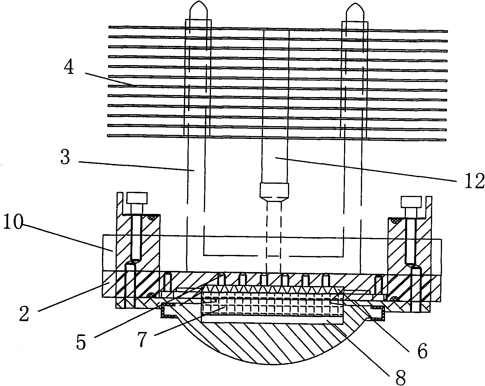
[0025] In the embodiment of the present invention, the honeycomb heat dissipation device 1 includes a ceramic substrate 2 sintered with a pure silver thermal conduction layer at the bottom, a heat dissipation pipe 3 at least partially in contact with the substrate, a heat dissipation fin 4 in contact with the heat dissipation pipe 3, and It also includes a mounting base 10 that is at least partially in contact with the substrate for fixing the heat dissipation pipe 3; the heat conduction layer 14 desc...

Embodiment 2

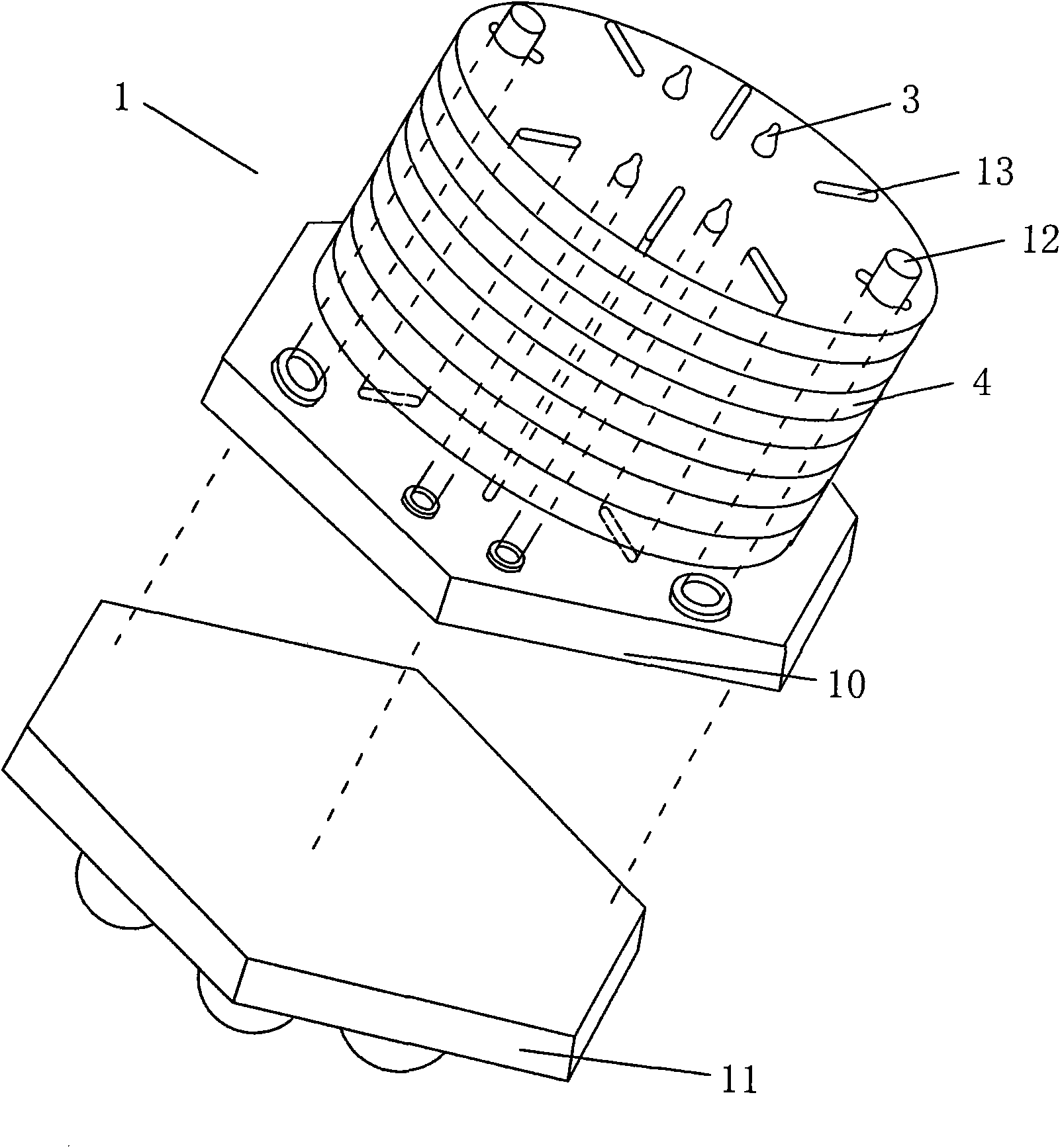
[0033] Such as Figure 1b and 2bAs shown, in the embodiment of the present invention, a copper mounting plate 11 is added between the mounting base 10 and the substrate, and the rest are the same as in Embodiment 1. The copper mounting plate 11 can be used to fix the LED lighting device or The uniformity of heat dissipation can be improved, and the heat can be evenly conducted to the honeycomb heat dissipation device 1 .

[0034] The heat dissipation method of the LED lamp of the present invention comprises the following steps:

[0035] S01. Transfer the heat of each LED light-emitting diode to the heat conduction layer through the heat conduction column, and then transfer the heat conduction layer to the heat dissipation pipe.

[0036] Specifically, the LED light-emitting diode transfers heat to the silver glue, and then the silver glue conducts to the heat-conducting column, and then the heat-conducting column transfers the heat to the heat-conducting layer, and finally th...


PUM


Abstract

The invention discloses a honeycomb-shaped heat radiator of an LED lamp fitting, which comprises a ceramic base plate, a heat radiation pipe and a heat radiation fin, wherein a heat conductive layer is sintered on the bottom of the ceramic base plate, at least partial of the heat radiation pipe is in contact with the base plate, and the heat radiation fin is in contact with the heat radiation pipe. The base plate is provided with at least two LED light emitting diodes, the ceramic base plate of the honeycomb-shaped heat radiator is in a shape of a regular polygon, preferably a regular hexagon, or the heat radiation fin is also in a shape of a regular polygon, so the placing number of the heat radiator in unit volume can be improved, and the heat radiation effect is further improved.

Description

technical field [0001] The invention relates to the technical field of heat dissipation of LED light-emitting diodes, in particular to a novel honeycomb heat dissipation device for LED lamps, which can effectively increase the number of radiators installed per unit volume and further improve the heat dissipation effect. Background technique [0002] Under the background of rising global energy shortage concerns, saving energy is an important issue we will face in the future. In the field of lighting, the application of LED light-emitting products is attracting the attention of the world. As a new type of green light source, LED It must be the trend of future development, so LED is called the fourth generation lighting source or green light source, which has the characteristics of energy saving, environmental protection, long life, small size, etc. Lighting and city night scenes and other fields. [0003] In recent years, some economically developed countries in the world ha...

Claims


Application Information

Patent Timeline
Patent Type & Authority Applications(China)
IPC IPC(8): F21V29/00F21V19/00F21Y101/02F21V29/71F21V29/76F21V29/87
Inventor 叶剑锋蒋建明顾佳
Owner 江苏尚恩光电科技有限公司
Why Eureka
Try Eureka