
Roller conveying device

A transmission device and roller technology, applied in the direction of rollers, transportation and packaging, conveyor objects, etc., can solve the problems of difficult maintenance, low reliability, and high difficulty in processing and assembly, and achieve uniform adsorption, simple structure, and overall structure simple effect

Pending Publication Date: 2022-04-12
ZHUHAI AUTO VISION TECH CO LTD
View PDF6 Cites 1 Cited by
  • Summary
  • Abstract
  • Description
  • Claims
  • Application Information

AI Technical Summary

Problems solved by technology

[0004] Due to the setting of multiple air holes in the roller at the present stage, it is necessary to ensure and adjust each air hole to achieve negative pressure. The roller is equipped with a complex air passage structure and switch structure, which is prone to uneven adsorption in the adsorption area, resulting in the adsorption of materials. Unstable situation; and the difficulty of processing and assembly is high, the reliability is low, and maintenance is difficult, etc.

Method used


Image

  • Roller conveying device
  • Roller conveying device
  • Roller conveying device

Examples


Embodiment Construction

[0022] Embodiments of the present invention are described in detail below, examples of which are shown in the drawings, wherein the same or similar reference numerals designate the same or similar elements or elements having the same or similar functions throughout. The embodiments described below by referring to the figures are exemplary only for explaining the present invention and should not be construed as limiting the present invention.

[0023] In the description of the present invention, if the first and the second are described only for the purpose of distinguishing technical features, it cannot be understood as indicating or implying relative importance or implicitly indicating the number of indicated technical features or implicitly indicating The sequence of the indicated technical features.

[0024] In the description of the present invention, unless otherwise clearly defined, words such as setting, installation, and connection should be understood in a broad sense...


PUM


Abstract

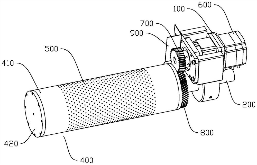
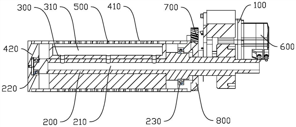
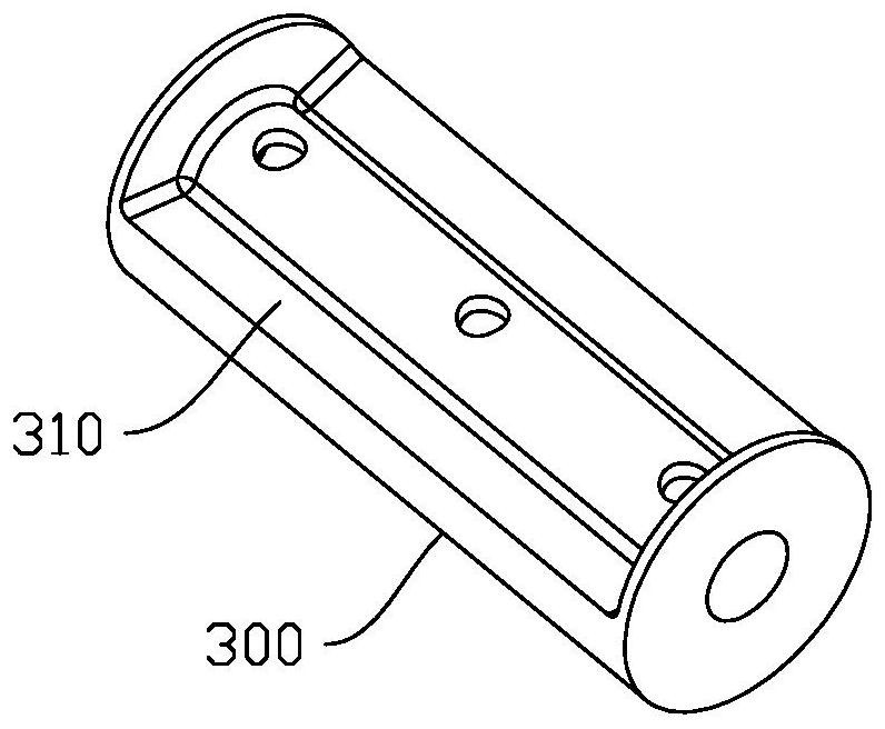
The invention discloses a roller conveying device. The roller conveying device comprises a supporting base, a ventilation shaft, an air distribution cylinder, a roller and a rotary driving mechanism. The ventilation shaft is connected with the supporting seat, and a main air channel is arranged in the ventilation shaft; an air distribution groove is formed in the surface of the outer circle of the air distribution cylinder, and the air distribution groove is communicated with the main air channel; the roller is rotatably arranged on the ventilation shaft in a sleeving mode and covers the air distribution cylinder, a plurality of evenly-distributed air holes are formed in the roller, and the air distribution groove is communicated with the air holes right opposite to the air distribution groove; the rotation driving mechanism is arranged on the supporting base, and the output end of the rotation driving mechanism is in transmission connection with the roller. And the orientation of the notch of the air distribution groove is the adsorption position and the conveying area of the material, and is the working area or the adsorption area of the roller. The air distribution channel of the roller conveying device is simple in structure, switching between the working state and the non-working state of the air holes is determined by the air distribution cylinder, and due to the fact that the air holes in the working area are communicated with the same air distribution groove, adsorption force of the air holes in the working area is even.

Description

technical field [0001] The invention relates to the technical field of conveying, in particular to a roller conveying device. Background technique [0002] The adsorption roller is a device used to absorb materials. When the roller rotates, it can drive the material to move to realize the transmission of materials. The principle is: the pores on the surface of the roller are in a low pressure or negative pressure state, and the material is attached to the roller under the action of atmospheric pressure. The surface of the drum, and then realize the synchronous rotation of the material and the roller. [0003] MLCC (Multi-layer Ceramic Capacitors) is the English abbreviation of chip multilayer ceramic capacitors. The ceramic dielectric diaphragm (ceramic diaphragm) with the printed electrode (internal electrode) is stacked in a dislocation manner, and a ceramic chip is formed by one-time high-temperature sintering, and then a metal layer (external electrode) is sealed on bot...

Claims


Application Information

Patent Timeline
Patent Type & Authority Applications(China)
IPC IPC(8): B65G39/09B65G39/07B65G39/02
Inventor 郑艳文李东红曾胜邓文波王飞
Owner ZHUHAI AUTO VISION TECH CO LTD
Learn More