Tool and system for cleaning optical fiber drawing channel

A channel and optical fiber technology, which is applied in the tooling and system field of optical fiber drawing channel cleaning, can solve the problems of easy shaking of optical fiber drawing, easy dust pollution and other problems, and achieve the effect of uniform adsorption force, good convergence and collection, and enlarged range

Pending Publication Date: 2022-02-25
JIANGDONG TECH CO LTD +2
View PDF9 Cites 0 Cited by
  • Summary
  • Abstract
  • Description
  • Claims
  • Application Information

AI Technical Summary

Problems solved by technology

[0005] Therefore, the technical problem to be solved by the present invention is to overcome the defects in the prior art that the optical fiber drawing is easy to shake and the workshop is easily polluted by dust, so as to provide a tool and system for cleaning the optical fiber drawing channel

Method used


Image

  • Tool and system for cleaning optical fiber drawing channel
  • Tool and system for cleaning optical fiber drawing channel

Examples


Embodiment 1

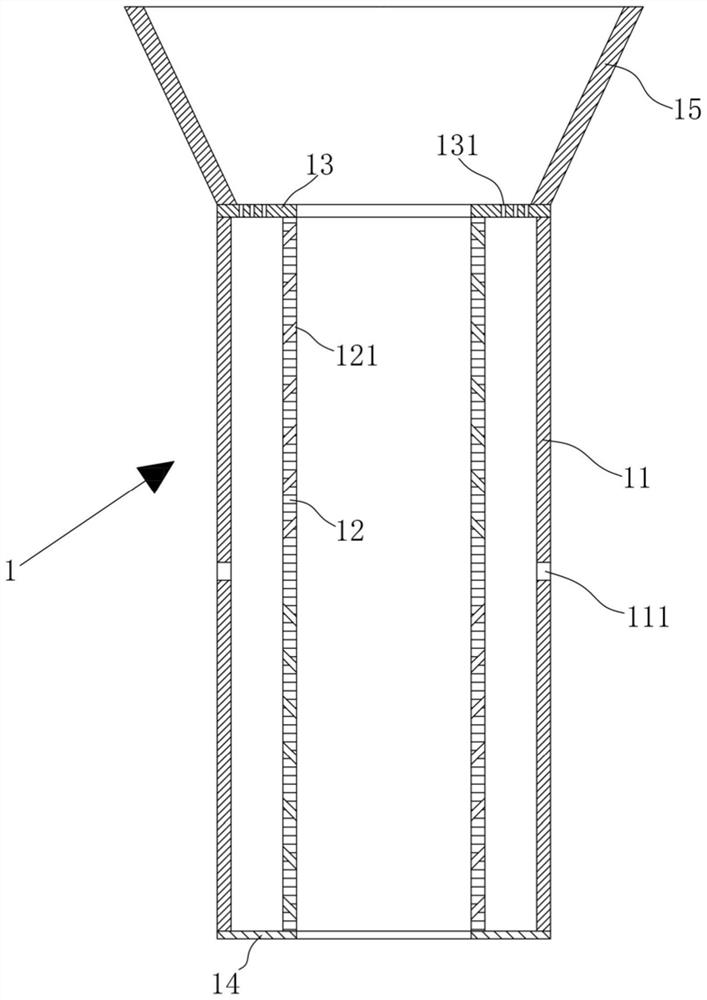
[0046] refer to figure 1 , this embodiment provides a tool for cleaning the optical fiber drawing channel, including an outer cylinder 11 , an inner cylinder 12 , an upper ring plate 13 and a lower ring plate 14 .

[0047] Wherein, the outer cylinder 11 is provided with at least two ports 111 , the ports 111 are suitable for externally connecting the negative pressure mechanism 3 , and all the ports 111 are evenly distributed along the circumference of the outer cylinder 11 . The main function of the interface 111 is to connect with the negative pressure mechanism 3 in use to form an air flow. The shape of the interface 111 is not limited here, and may be circular or square or other common shapes, depending on the shape of the joint of the negative pressure mechanism 3 . The arrangement form of the interface 111 can be only one circle in the axial direction of the outer cylinder 11, or two or more circles along the axial direction of the outer cylinder 11, but each circle mus...

Embodiment 2

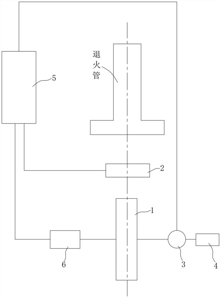
[0058] refer to figure 2 , this embodiment provides a system for cleaning the optical fiber drawing channel, including a wire diameter meter 2, a tooling 1, a negative pressure mechanism 3, a filter mechanism 4 and a controller 5.

[0059] Among them, the wire diameter meter 2 is a mature structure in the field, which is suitable for detecting the diameter of an optical fiber. It should be noted that, because it needs to cooperate with the controller 5, it is necessary to use the electronic wire diameter gauge 2 capable of sending signals.

[0060] Wherein, the tooling 1 adopts the structure as described in the first embodiment.

[0061] Wherein, the negative pressure mechanism 3 can adopt common structures such as a vacuum machine and an exhaust fan, and the negative pressure mechanism 3 is provided with an input port and an output port, and its input port is connected with the interface 111, so that a negative pressure is formed in the dust discharge channel, thereby remov...


PUM


Abstract

The invention relates to the technical field of optical fiber drawing equipment, in particular to a tool and system for cleaning an optical fiber drawing channel. The tool and system for cleaning the optical fiber drawing channel comprise an outer cylinder, an inner cylinder, an upper annular plate and a lower annular plate, wherein the outer cylinder is provided with at least two connectors, the connectors are suitable for being externally connected with a negative pressure mechanism, and all the connectors are evenly distributed in the circumferential direction of the outer cylinder; a through cavity suitable for optical fibers to pass through is formed in the inner cylinder, the inner cylinder is coaxially arranged in the outer cylinder, the inner cylinder and the outer cylinder are arranged at intervals to form a dust discharging channel with an annular section, and air holes are evenly distributed in the inner cylinder; the upper annular plate covers the upper end surface of the dust discharging channel in a sealing manner; and the lower annular plate covers the lower end surface of the dust discharging channel in a sealing manner. According to the tool and system for cleaning the optical fiber drawing channel, optical fibers can be effectively prevented from shaking; and meanwhile, dust cannot be diffused into the workshop, so that the cleanliness of the workshop is guaranteed.

Description

technical field [0001] The invention relates to the technical field of optical fiber drawing equipment, in particular to a tool and system for cleaning optical fiber drawing channels. Background technique [0002] In the production process of optical fiber drawing, the graphite parts and graphite carbon felt in the drawing furnace are baked at high temperature for a long time, and graphite dust will be generated and fall from the annealing tube along with the optical fiber. The dust will reduce the overall cleanliness of the production workshop and hinder the cleanliness maintenance of the workshop; moreover, if the dust adheres to the surface of the optical fiber, it will also affect the overall quality of the optical fiber and cause economic losses. [0003] At present, the optical fiber cleaning system used in the workshop is an optical fiber 100-level purification system. This system uses multiple air blowing fans, which are arranged longitudinally under the annealing tu...

Claims


Application Information

Patent Timeline
IPC IPC(8): B08B5/04B08B15/02B08B13/00C03B37/02
CPCB08B5/043B08B15/02B08B13/00C03B37/02B08B2240/02
Inventor 盖旭梁江宇张柳兵朱刘盅曹珊珊薛驰薛济萍
Owner JIANGDONG TECH CO LTD
Why Eureka
Try Eureka