Automatic turnover device for crane supporting leg
An automatic flipping and crane technology, applied in cranes and other directions, can solve the hidden troubles of pipelines and hydraulic components, high cost, complicated operation and other problems, and achieve the effect of convenient packaging and transportation, and space saving.
- Summary
- Abstract
- Description
- Claims
- Application Information
AI Technical Summary
Problems solved by technology
Method used
Image

Examples
Embodiment 1
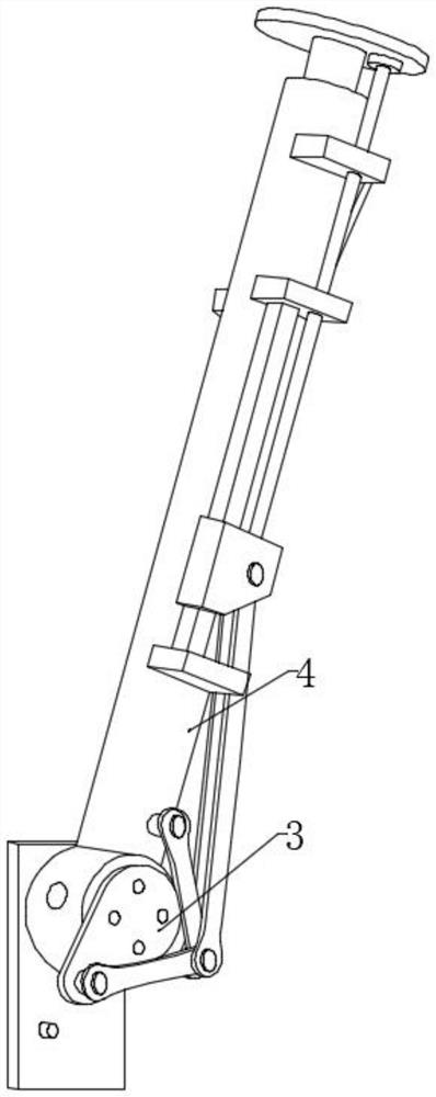
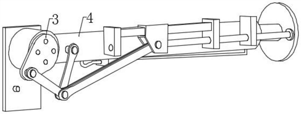
[0030] refer to Figure 1-3 , the automatic overturning device for the outriggers of the crane, including: installing the fixed plate 1, the horizontal outrigger 2, fixedly installed on the front surface of the fixed plate 1; One side; the vertical hydraulic cylinder 4 is fixed on the surface of the horizontal leg 2, and the lower end of the vertical hydraulic cylinder 4 is equipped with a telescopic vertical leg 9;
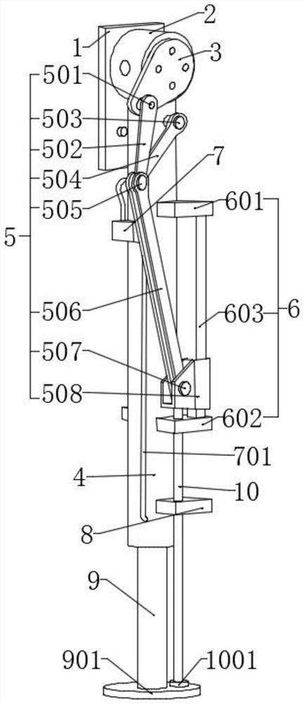
[0031] Among them, the vertical hydraulic cylinder 4 and the vertical leg hinge seat 3 are provided with a linkage linkage mechanism 5 that cooperates with each other. The lower end of the linkage linkage mechanism 5 is fixedly connected with a sliding push rod 10, and the surface of the vertical hydraulic cylinder 4 is fixedly installed. There is a guide mechanism 6, and the vertical hydraulic cylinder 4 is positioned at the lower outer wall of the guide mechanism 6 and the limit slider 8 is fixedly installed.
[0032] In the present invention, the fixed plate ...
Embodiment 2
[0034] refer to Figure 1-3, the automatic overturning device for the legs of the crane is basically the same as that of Embodiment 1, and furthermore, the horizontal support leg 2 is fixedly installed with the crane body by installing the fixed plate 1, and the horizontal support leg 2 is fixedly installed with the fixed plate 1 by the welding rod; linkage The link mechanism 5 includes the first rotating shaft 501, the first connecting rod 502, the second rotating shaft 503, the second connecting rod 504, the third rotating shaft 505, the third connecting rod 506, the fourth rotating shaft 507 and the sliding base 508, the first One end of the connecting rod 502 is fixedly installed with the No. 1 rotating shaft 501, and the other end of the first connecting rod 502 is fixedly installed with the No. 3 rotating shaft 505. The surface of the No. 3 rotating shaft 505 is located on both sides of the first connecting rod 502, and the third connecting rod is movably installed. 506,...
Embodiment 3
[0037] refer to Figure 1-3 , the automatic overturning device for the outriggers of the crane, including the installation of the fixed plate 1, the front surface of the fixed plate 1 is fixedly installed with the horizontal outrigger 2, the other end of the horizontal outrigger 2 is fixedly installed with the vertical outrigger hinge seat 3, and the horizontal outrigger 2 The surface of the vertical hydraulic cylinder 4 is fixedly installed, the surface of the vertical leg hinge seat 3 is movably connected with a linkage linkage mechanism 5, the surface of the vertical hydraulic cylinder 4 is fixedly installed with a guide mechanism 6, and the surface of the vertical hydraulic cylinder 4 A control device 7 is fixedly installed on one side of the guide mechanism 6, a limit slider 8 is fixedly installed on the surface of the vertical hydraulic cylinder 4 below the guide mechanism 6, and a telescopic vertical support leg 9 is movably installed at the lower end of the vertical hyd...
PUM
 Abstract
Description
Claims
Application Information