Temporary drainage device for construction site and implementation method of temporary drainage device

A technology for drainage devices and construction sites, which is applied to water supply devices, waterway systems, and sewer pipeline systems, etc., can solve problems such as affecting safe and civilized construction and subsequent construction procedures, destroying structural integrity, and increasing flooded area, so as to maintain the building Beautiful structure, does not affect the safety of the structure, and improves the effect of safety

Pending Publication Date: 2022-04-12
中国建筑工程(澳门)有限公司
View PDF0 Cites 1 Cited by
  • Summary
  • Abstract
  • Description
  • Claims
  • Application Information

AI Technical Summary

Problems solved by technology

[0007] (3) The opening of the floor slab and the removal of the concrete structure at the edge of the floor destroy the structural integrity. In severe cases, the structural safety will be affected
[0008] (4) Water accumulated on the floor flows into the next floor along the open floor hole and the edge of the damaged floor, resulting in water accumulation in the lower floor, and the next floor needs to destroy the structure again for drainage
[0009] (5) Unorganized drainage methods that damage the structure, such as opening holes in the floor and knocking off the edge of the floor, will lead to an increase in the flooded area of ​​the building, seriously affecting safe and civilized construction and the development of subsequent construction procedures

Method used


Image

  • Temporary drainage device for construction site and implementation method of temporary drainage device
  • Temporary drainage device for construction site and implementation method of temporary drainage device
  • Temporary drainage device for construction site and implementation method of temporary drainage device

Examples


Embodiment Construction

[0048] The following will clearly and completely describe the technical solutions in the embodiments of the present invention with reference to the accompanying drawings in the embodiments of the present invention. Obviously, the described embodiments are only some, not all, embodiments of the present invention. Based on the embodiments of the present invention, all other embodiments obtained by persons of ordinary skill in the art without making creative efforts belong to the protection scope of the present invention.

[0049] see Figure 1-6 , an embodiment provided by the present invention:

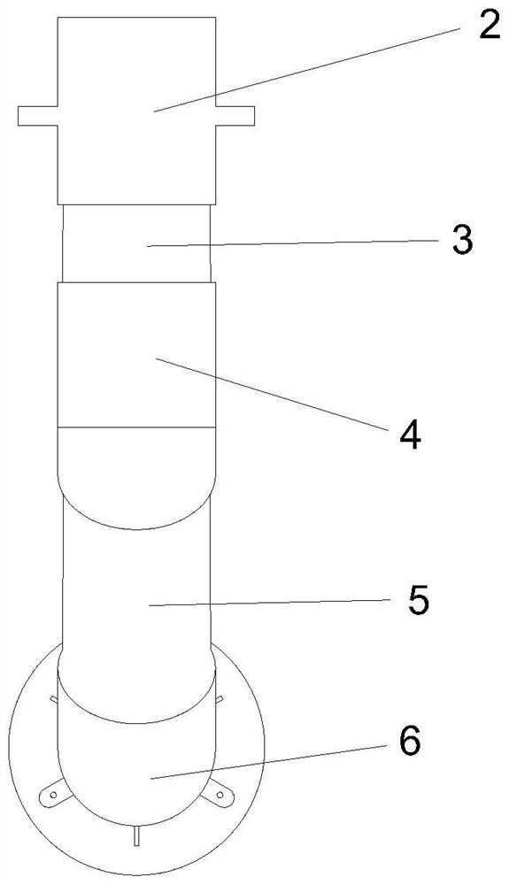
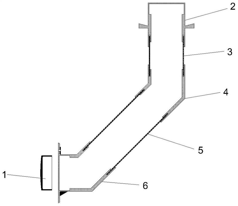
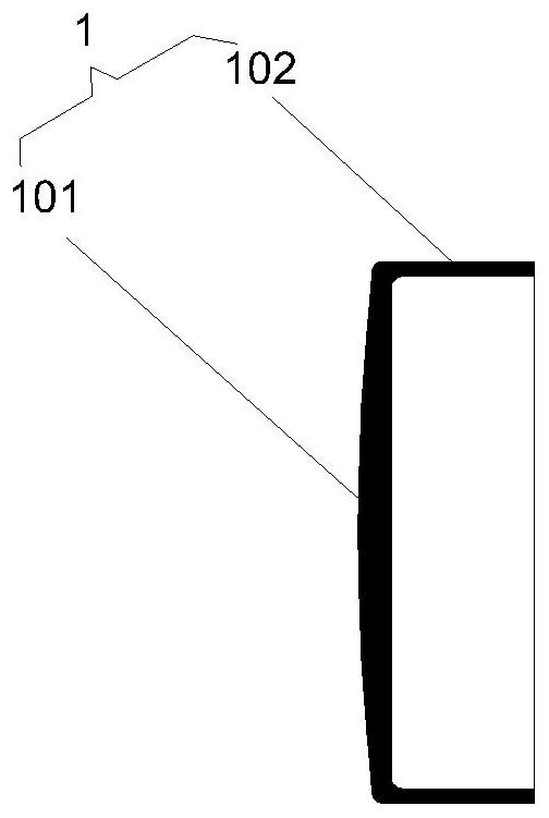
[0050] A temporary drainage device on a construction site. The temporary drainage device includes an end plugging cover plate component, a socket water stop section component, a vertical straight pipe section component, a socket elbow component, an oblique straight pipe section component, a socket fixing Elbow parts, socket water-stop joint parts, vertical straight pipe section parts,...


PUM


Abstract

The invention relates to the field of on-site construction of constructional engineering, in particular to a temporary drainage device for a construction site and an implementation method thereof.The temporary drainage device comprises an end plugging cover plate component, a socket water stop joint component, a vertical straight pipe section component, a socket elbow component, an inclined straight pipe section component and a socket fixed elbow component; the socket water stop section component and the socket elbow component are connected through a vertical straight pipe section component, the socket elbow component and the socket fixed elbow component are connected through an inclined straight pipe section component, and the socket fixed elbow component is further provided with an end plugging cover plate component. The temporary drainage device is installed in a pre-buried mode, compared with a traditional mode that drainage is conducted through holes, a pre-buried pipeline is not damaged, so that an exposed wire pipe needs to be laid again due to the fact that the wire pipe cannot penetrate in the later period, and the fire-fighting potential safety hazard caused by the fact that the fire-resistant time of the exposed wire pipe is shorter than that of a concealed laid wire pipe in a floor is eradicated; and the safety is higher.

Description

technical field [0001] The invention relates to the field of construction site construction, in particular to a temporary drainage device on a construction site and an implementation method thereof. Background technique [0002] At present, there are a large number of temporary water links in the construction of construction projects. For example, the concrete structure after pouring needs wet operations such as water spraying maintenance, wall plastering and grouting. In addition, during the construction process of the construction project, it cannot be closed, and rainfall will also fall into the interior of the building. Since the construction in progress does not have the conditions to install permanent drainage facilities, a large amount of waste water and rainwater generated during the production process will accumulate in the floors, seriously affecting safe and civilized construction and the development of subsequent construction procedures. How to do a good job of...

Claims


Application Information

Patent Timeline
IPC IPC(8): E03F3/04
Inventor 马圣毅夏家华满效强陈耀郑伟玲王锦翊
Owner 中国建筑工程(澳门)有限公司
Why Eureka
Try Eureka