Front dumper double-seal hydraulic oil cylinder

A technology for sealing hydraulic pressure and dump trucks, which is applied in the field of hydraulic cylinder sealing, which can solve the problems of inconvenient replacement of sealing rings and achieve the effect of ensuring pressure difference

Pending Publication Date: 2022-04-12
山东福阳液压科技有限公司
View PDF1 Cites 0 Cited by
  • Summary
  • Abstract
  • Description
  • Claims
  • Application Information

AI Technical Summary

Problems solved by technology

[0005] The purpose of the present invention is to provide a front-mounted dump truck double-channel sealed hydraulic cylinder, which is convenient to take out the guide sleeve from the cylinder head and replace the sealing ring, which solves the problem that it is inconvenient to replace the sealing ring when the sealing ring is damaged. question

Method used


Image

  • Front dumper double-seal hydraulic oil cylinder
  • Front dumper double-seal hydraulic oil cylinder
  • Front dumper double-seal hydraulic oil cylinder

Examples


Embodiment 1

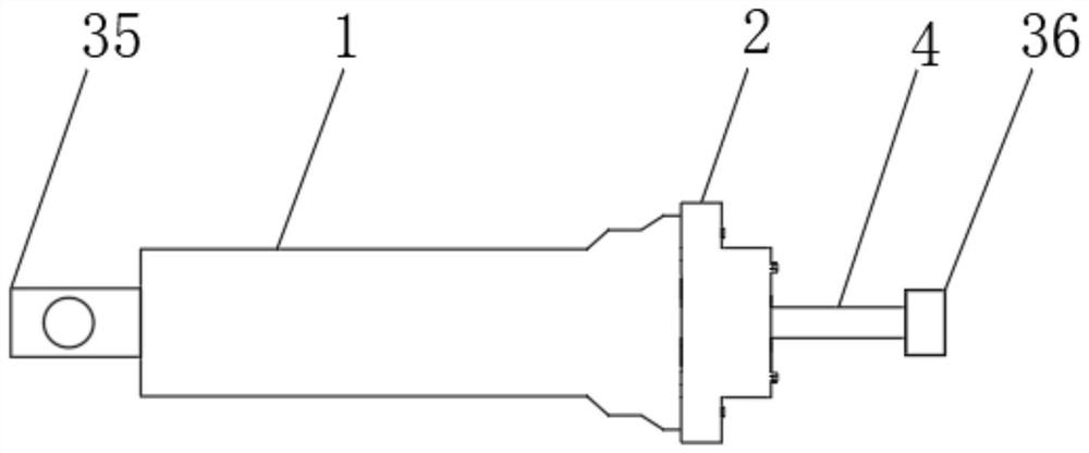
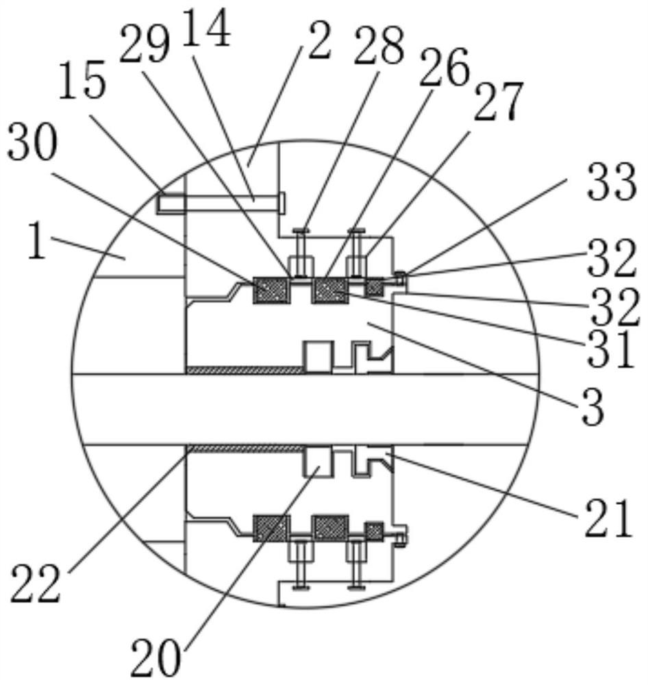
[0030] see Figure 1 to Figure 5 , the present invention provides a technical solution: a front-mounted dump truck double-channel sealed hydraulic cylinder, including a hydraulic cylinder block 1 and a cylinder head 2, the cylinder head 2 is installed on the right end of the hydraulic cylinder block 1, and the cylinder head 2 is sleeved with a guide sleeve 3, and the interior of the hydraulic cylinder 1 is provided with a piston rod 4 that penetrates the guide sleeve 3 and extends to the cylinder head 2;

[0031] The inner wall of the guide sleeve 3 is sequentially provided with a guide sleeve first groove 23, a guide sleeve second groove 24 and a guide sleeve third groove 25 from left to right;

[0032] The inner top wall and inner bottom wall of the cylinder head 2 are symmetrically provided with rectangular gaps 26, and the outer end of each rectangular gap 26 is provided with two extension grooves 27, and the top and bottom of the guide sleeve 3 are screwed with two groove...

Embodiment 2

[0040] Embodiment two, the difference with embodiment one is:

[0041] Specifically, the left side of the hydraulic cylinder block 1 is provided with a mounting seat 35, and the right end of the piston rod 4 is provided with a connecting seat 36. The mounting seat 35 provided is used to realize the installation work of the hydraulic cylinder block 1. The connecting seat The setting of 36 is used to connect the parts that need to be telescopic.

[0042] Working principle: when replacing the first sealing ring 30 of the cylinder head, the second sealing ring 31 of the cylinder head, and the third sealing ring 32 of the cylinder head on the guide sleeve 2, Only need to unscrew some locking bolts 14, and unscrew the threaded rods and nuts on the first flange plate 33 and the second flange plate 34, then by manually rotating the threaded column 28, utilize the threaded column 28 and the cylinder head 2 Screw connection, the position of spacer 29 can be adjusted, spacer 29 is moved...


PUM


Abstract

The invention discloses a front dumper double-seal hydraulic oil cylinder, and relates to the technical field of hydraulic oil cylinder sealing, the front dumper double-seal hydraulic oil cylinder comprises a hydraulic cylinder body and a cylinder cover, the cylinder cover is installed at the right end of the hydraulic cylinder body, a guide sleeve is sleeved with the cylinder cover, and a piston rod penetrating through the guide sleeve and extending out of the cylinder cover is arranged in the hydraulic cylinder body; a first guide sleeve groove, a second guide sleeve groove and a third guide sleeve groove are sequentially formed in the inner wall of the guide sleeve from left to right, and rectangular notches are symmetrically formed in the inner top wall and the inner bottom wall of the cylinder cover. The guide sleeve can be taken out from the cylinder cover only by screwing off a plurality of locking bolts, screwing off threaded rods and nuts on the first flange plate and the second flange plate, manually rotating a threaded column, utilizing threaded connection of the threaded column and the cylinder cover, adjusting the position of a spacer block, moving the spacer block into an extension groove, and then knocking by means of an external workpiece.

Description

technical field [0001] The invention relates to the technical field of hydraulic oil cylinder sealing, in particular to a double-channel sealed hydraulic oil cylinder of a front-mounted dump truck. Background technique [0002] The hydraulic cylinder is mainly used for various types of dump trucks. It adopts a single-acting telescopic sleeve hydraulic cylinder. However, the hydraulic cylinders currently used are all single-channel oil seals. The sealing performance of the oil seal is not good enough. The damage of the sealing ring will cause scratches on the cylinder and reduce the service life of the cylinder. [0003] According to the patent CN202020109797.X, a front-mounted dump truck double-channel sealed hydraulic cylinder relates to the technical field of hydraulic cylinders, including a cylinder assembly, and the cylinder assembly is provided with a cylinder, wherein the cylinder assembly is provided with a stage hydraulic cylinder, secondary hydraulic cylinder, tert...

Claims


Application Information

Patent Timeline
Patent Type & Authority Applications(China)
IPC IPC(8): F15B15/14
Inventor 冯起吕怀健杨绍安庞世伟徐福阳宋成凯杨诗舟徐以成武玉林
Owner 山东福阳液压科技有限公司
Why Eureka
Try Eureka