Electromagnetic control stepless speed change door opening and closing refrigerator

A technology of infinitely variable speed and electromagnetic control, applied in household refrigeration devices, coolers, household refrigerators, etc., can solve the problems of occupying a large space, increasing the overall volume and weight of the freezer, and high noise, and achieves a higher degree of automation. The effect of saving maintenance trouble and low cost

Pending Publication Date: 2022-04-12
AUCMA +1
8 Cites 0 Cited by

AI-Extracted Technical Summary

Problems solved by technology

Among them, the use of manual opening and closing of the door is a relatively traditional and old-fashioned way, which cannot be automated or remotely controlled.
However, the mechanical structure of the horizontal switch door driven by a motor is too complicated. It must have a driving structure, a transmission structure, a ...

Method used

[0039] Further, the cabinet door 2 includes an outer frame 21, and one end of the outer frame 21 away from the other cabinet door 2 is integrally formed with a handle 211, which facilitates manual door opening and closing operations through the handle 211.
[004...

Abstract

The invention relates to the technical field of refrigerators, in particular to an electromagnetic control stepless speed change door opening and closing refrigerator which comprises a main cabinet body, two cabinet doors are slidably connected into a cabinet opening in the top end of a cabinet body shell of the main cabinet body, electromagnet sets are arranged in the front side wall and the rear side wall of the cabinet opening of the cabinet body shell, and each electromagnet set comprises a plurality of electromagnets. An electric insulation rubber plate is clamped between every two adjacent electromagnets, armatures are embedded in the side walls of the front side and the rear side of the cabinet door, and a single-chip microcomputer control circuit board is further arranged in the main cabinet body. According to the electromagnetic control stepless speed change door opening and closing refrigerator, the electromagnetic principle is used for driving, no complex mechanical mechanism is needed, the refrigerator is small in size and low in manufacturing cost, the maintenance and management trouble caused by mechanical structure faults is omitted, and the refrigerator door is smooth and free of noise in the opening and closing process; the single chip microcomputer is used for controlling opening and closing of the cabinet door, the automation degree of opening and closing of the cabinet door is improved, the remote control function can be achieved, and the problems existing in the manual and common mechanical structure application process are effectively solved.

Application Domain

Lighting and heating apparatusDomestic refrigerators

Technology Topic

Microcomputer controlAutomation +1

Image

  • Electromagnetic control stepless speed change door opening and closing refrigerator
  • Electromagnetic control stepless speed change door opening and closing refrigerator
  • Electromagnetic control stepless speed change door opening and closing refrigerator

Examples

  • Experimental program(1)

Example Embodiment

[0031] The technical solutions in the present invention will be clearly and completely described below with reference to the accompanying drawings of the present invention. Obviously, the described inventions are only a part of the inventions of the present invention, but not all of them. Based on the inventions in the present invention, all other inventions obtained by those of ordinary skill in the art without creative work fall within the protection scope of the present invention.
[0032] In the description of the present invention, it should be understood that the terms "length", "upper", "lower", "front", "rear", "left", "right", "horizontal", "top", " The orientation or positional relationship indicated by "bottom", "inside", "outside", etc. is based on the orientation or positional relationship shown in the drawings, and is only for the convenience of describing the present invention and simplifying the description, rather than indicating or implying the equipment or Elements must have a particular orientation, be constructed and operate in a particular orientation and are therefore not to be construed as limitations of the invention.
[0033] In addition, in the description of the present invention, "a number of" means at least two, such as two, three, etc., unless expressly and specifically defined otherwise.
[0034] see Figure 1-Figure 7 , the present invention provides a kind of technical scheme:
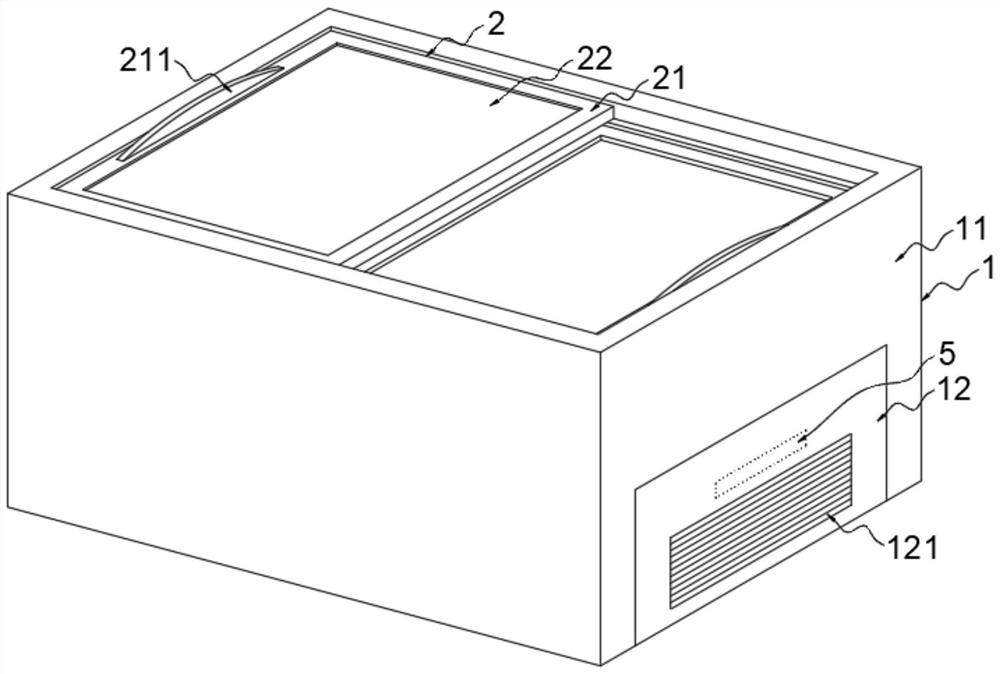
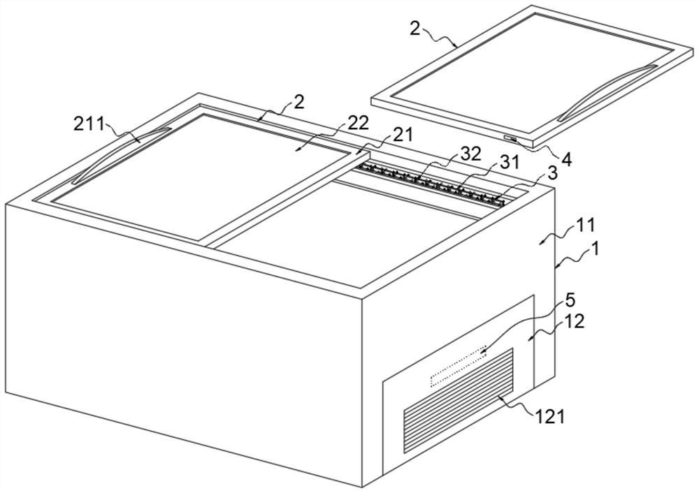
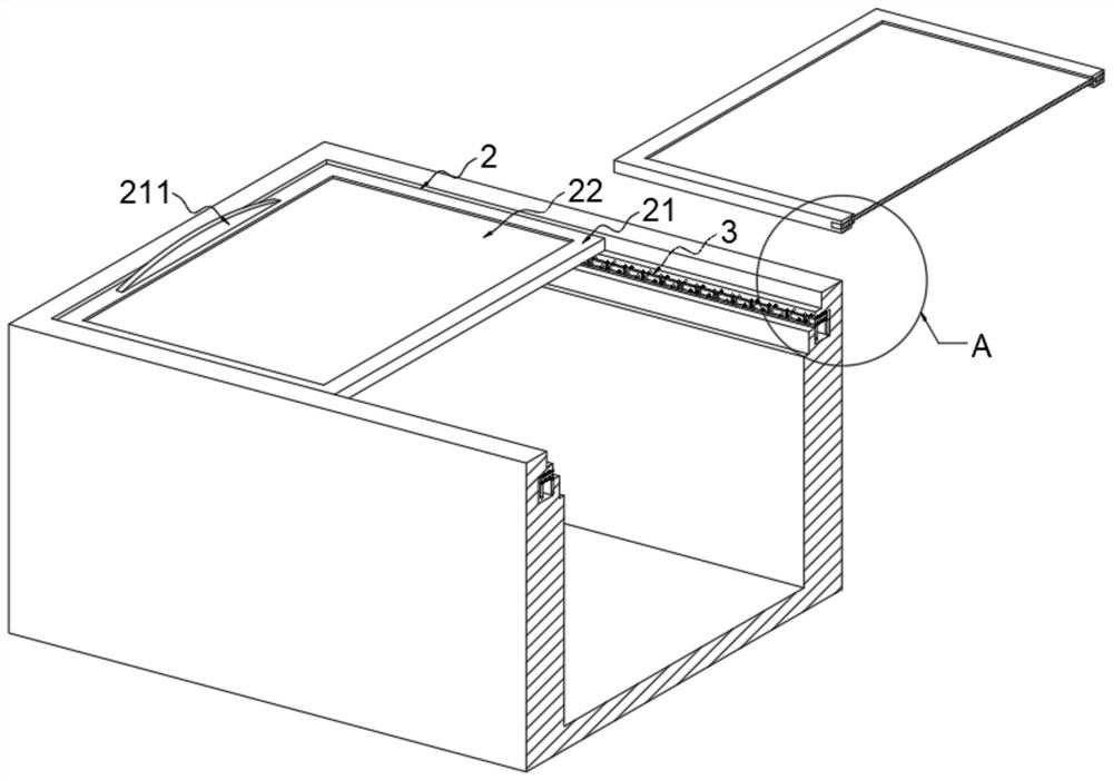
[0035] The electromagnetically controlled stepless variable speed switch door refrigerator includes a main cabinet 1, the main cabinet 1 includes a cabinet shell 11, and two cabinet doors 2 are slidably connected to the top cabinet opening of the cabinet shell 11. The cabinet of the cabinet shell 11 The front and rear side walls of the door are provided with electromagnet groups 3, and the electromagnet group 3 includes a number of electromagnets 31, and an electrical insulating rubber plate 32 is sandwiched between two adjacent electromagnets 31. Armatures 4 are embedded in all of them, and a single-chip control circuit board 5 is also arranged in the main cabinet 1 .
[0036] In this embodiment, an equipment box cover 12 is provided at the lower end of one side outer wall of the cabinet body 11 , wherein the equipment box cover 12 is an equipment box inside, which is used to install equipment such as refrigerators and motors of the freezer.
[0037] Further, a heat dissipation port 121 is provided in the middle of the equipment box cover 12 for heat dissipation of the refrigerator.
[0038] In this embodiment, the two cabinet doors 2 are staggered up and down, and the two cabinet doors 2 are in sliding contact with each other, which is the same as the structural design of a conventional refrigerator.
[0039] Further, the cabinet door 2 includes an outer frame 21 , and an end of the outer frame 21 away from the other cabinet door 2 is integrally formed with a handle 211 , which facilitates manual door opening and closing operations through the handle 211 .
[0040] Further, a glass plate 22 is fixed and embedded in the outer frame 21 , and it is convenient to directly view the inside of the refrigerator from the outside through the glass plate 22 .
[0041] In this embodiment, the electromagnet 31 includes an iron core 311 , and a coil 312 is wound around the outside of the iron core 311 . When the coil 312 is energized, the electromagnet 31 can generate magnetism, thereby attracting the armature 4 .
[0042] Further, the armature 4 is fixedly embedded in the side wall of the outer frame 21 , so that the armature 4 is strong and stable, and at the same time, it is convenient to attract the armature 4 through the electromagnet 31 to drive the cabinet door 2 to move.
[0043] Further, when the cabinet door 2 is installed in the cabinet opening of the main cabinet 1, the armature 4 corresponds to the horizontal position of the electromagnet group 3 corresponding to its position, and the armature 4 abuts against the iron core 311 corresponding to its position.
[0044] Specifically, during the sliding opening of the cabinet door 2 , the armature 4 moves along the distribution direction of the electromagnets 31 in the electromagnet group 3 .
[0045] Specifically, the length of the armature 4 is greater than the length of the iron core 311, so that after the armature 4 is attracted to a designated position by one of the electromagnets 31, the front and rear ends of the armature 4 extend to the electromagnets 31 in adjacent positions, respectively. After the electromagnet 31 at the adjacent position is electrified to generate magnetism, the armature 4 can be attracted sensitively, so that the armature 4 can react quickly and move in the direction of the electrified electromagnet 31 .
[0046] In this embodiment, the single-chip control circuit board 5 is installed inside the equipment box cover 12, so that the single-chip control circuit board 5 can be connected with the original circuit board/circuit of the refrigerator.
[0047] Specifically, the coil 312 is connected to the controller through a power line, and the controller is signal-connected to the single-chip control circuit board 5 through a signal line, so that the single-chip control circuit board 5 can sequentially control the power on and off process of each electromagnet 31 through the controller.
[0048] Among them, a number of electromagnets 31 start from the position close to the edge of the cabinet and are numbered in the middle. When the cabinet door 2 is opened, the power-on and power-off operations are performed in sequence according to the numbering sequence of the electromagnets 31. When the cabinet door 2 is closed, according to the serial number The power-on and power-off operations are performed in reverse order.
[0049] Specifically, the working principle of the electromagnet group 3 and the armature 4 to realize the opening and closing process of the cabinet door 2 is as follows:
[0050] The first electromagnet 31 generates magnetism after being energized, and the magnetized electromagnet 31 will attract the nearby armature 4. The armature 4 is installed together with the cabinet door 2, and the cabinet door 2 will move towards the energized electromagnet along with the armature 4. The direction of the iron 31 moves; when the cabinet door 2 moves to an appropriate position, the first electromagnet 31 is powered off and the second electromagnet 31 is powered on. Under the inertia of the cabinet door 2 moving forward, the second electromagnet 31 is powered on. 31 will continue to attract the armature 4 in the cabinet door 2, thereby driving the cabinet door 2 to continue to move forward, and so on, until the electromagnet 3 at the end attracts the armature 4; when the door is closed, the power-on sequence of the electromagnet 31 is reversed , until fully closed.
[0051] The on-off time of each electromagnet 31 is adjusted by the single-chip control circuit board 5;
[0052]In addition, the single-chip control circuit board 5 controls the on-off time of the electromagnet 31. The shorter the on-off time, the faster the running speed of the cabinet door 2, and the stepless speed change can also be realized;
[0053] The single-chip control circuit board 5 changes the direction of opening and closing the door by receiving the signal from the outside, opening or closing the door;
[0054] If the single-chip microcomputer control circuit board 5 adopts a high-end single-chip microcomputer, the door switch at any position can be realized;
[0055] Furthermore, if the single-chip control circuit board 5 can receive an external WIFI signal, the process of remotely controlling the door opening and closing can be realized.
[0056] In addition, it is worth noting that the structure of the single-chip microcomputer control circuit board 5 and the process of programming the same are known to those skilled in the art, and will not be repeated here.
[0057] In addition, it is worth noting that the combination of the electromagnet group 3 and the armature 4 can be set to one group, two groups or four groups;
[0058] Among them, when only one set is set, the opening and closing of one of the cabinet doors 2 can only be controlled by one side, but the cabinet door may be shifted or moved sluggishly during the opening and closing process; when two sets are set, the two sides can be controlled simultaneously. Control the opening and closing of one of the cabinet doors 2 to make the opening and closing smoother, or you can control the opening and closing of the two cabinet doors 2 only through one side; when four groups are set, you can control the opening and closing of the two cabinet doors 2 through both sides. Open and close, so that both cabinet doors 2 can be automatically opened and closed smoothly.
[0059] When the electromagnetically controlled stepless variable speed switch door refrigerator of the present invention is in use, the main cabinet body 1 is first energized to make it run normally, and when the cabinet door 2 needs to be opened, the single-chip control circuit board 5 controls the electromagnets in sequence through the controller in sequence of numbers. The power supply of 31 is turned on and off, the energized electromagnet 31 attracts the armature 4 to drive the cabinet door 2 to move, so that the cabinet door 2 moves along the direction of the electromagnet group 3 until the cabinet door 2 is fully opened; The control circuit board 5 controls the power on and off of the electromagnets 31 through the controller in the reverse sequence of numbers until the cabinet door 2 is completely closed.
[0060] The foregoing has shown and described the basic principles, main features and advantages of the present invention. Those skilled in the art should understand that the present invention is not limited by the above-mentioned inventions. The above-mentioned inventions and descriptions in the specification are only preferred examples of the present invention, and are not intended to limit the present invention, without departing from the spirit and scope of the present invention. , the present invention will also have various changes and improvements, and these changes and improvements all fall within the scope of the claimed invention. The claimed scope of the present invention is defined by the appended claims and their equivalents.

PUM

no PUM

Description & Claims & Application Information

We can also present the details of the Description, Claims and Application information to help users get a comprehensive understanding of the technical details of the patent, such as background art, summary of invention, brief description of drawings, description of embodiments, and other original content. On the other hand, users can also determine the specific scope of protection of the technology through the list of claims; as well as understand the changes in the life cycle of the technology with the presentation of the patent timeline. Login to view more.

Similar technology patents

Wind generating set

InactiveCN101363407Acompact structurereduce volume
Owner:SANY ELECTRIC CO LTD

Video coding apparatus

ActiveUS20070217507A1reduce volumereduce image quality
Owner:FUJITSU LTD

Classification and recommendation of technical efficacy words

  • reduce volume
  • low cost

Implant release mechanism

ActiveUS20080140178A1reduce volumereduce outer diameter
Owner:COOK MEDICAL TECH LLC

Speed reduction box for turbine fracturing

Owner:YANTAI JEREH PETROLEUM EQUIP & TECH

Miniature and Multi-Band RF Coil Design

ActiveUS20100090824A1reduce volumelong wavelength
Owner:HONG KONG APPLIED SCI & TECH RES INST

Automatic washing and dewatering combined device of rotary type mop

InactiveCN102370447Areduce volumeSimple structure
Owner:上海祥美网络科技有限公司 +1

Optical imaging system

ActiveUS20070008625A1reduce volumedeteriorate with time
Owner:SAMSUNG ELECTRONICS CO LTD

System and method for transmitting wireless digital service signals via power transmission lines

ActiveUS7929940B1reduce bandwidth requirementlow cost
Owner:NEXTEL COMMUNICATIONS

System and method for determination of position

InactiveUS20090149202A1low costreduce requirement
Owner:STEELE CHRISTIAN

Adaptive antenna optimization network

InactiveUS6961368B2low costminimal space
Owner:ERICSSON INC

Antenna device and method for attaching the same

ActiveUS20150138022A1low costimproved strength characteristic
Owner:NEC CORP
Why Eureka
Try Eureka