Environmental noise monitoring device capable of distinguishing noise source direction
A technology for environmental noise and monitoring devices, applied in measuring devices, measuring ultrasonic/sonic/infrasonic waves, chemical instruments and methods, etc., can solve problems such as inconvenient noise source processing and cumbersome noise monitoring, and achieve the effect of improving efficiency
- Summary
- Abstract
- Description
- Claims
- Application Information
AI Technical Summary
Problems solved by technology
Method used
Image
Examples
Embodiment 1
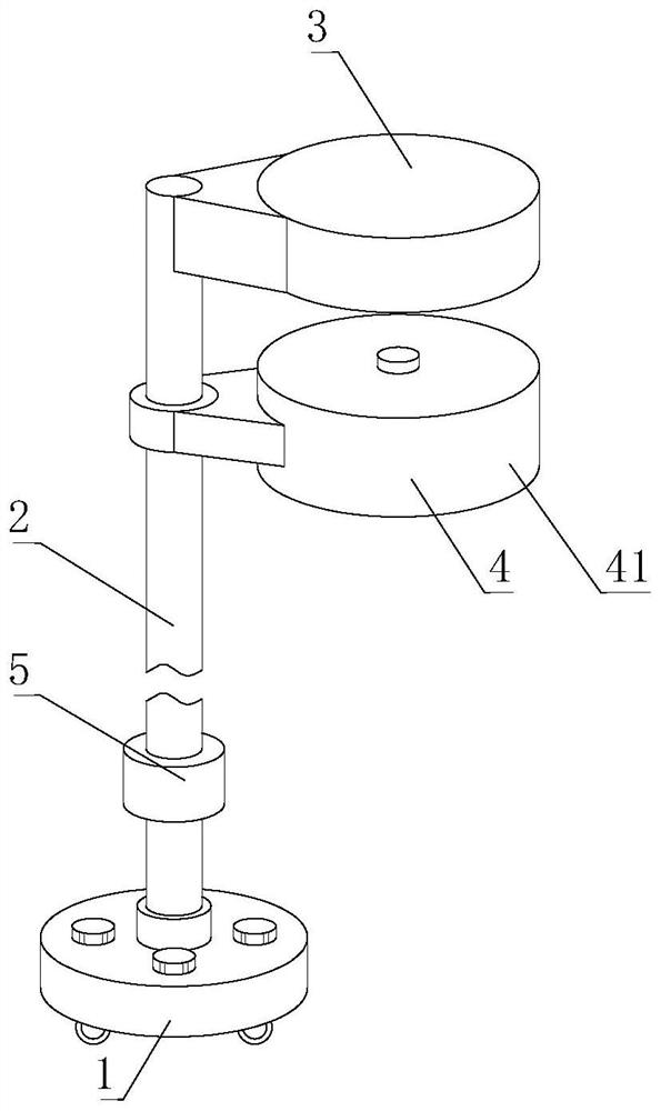
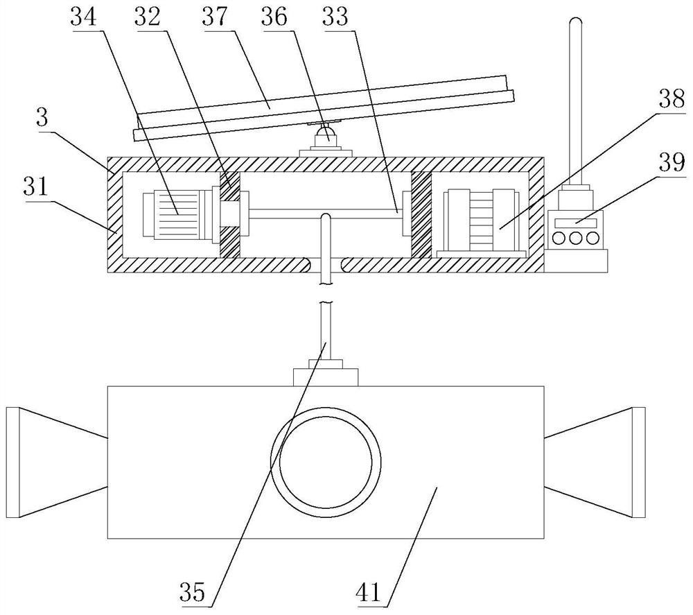
[0035] Such as Figure 1-7As shown, the present invention provides an environmental noise monitoring device capable of distinguishing the direction of the noise source, comprising a mobile base 1, the top of the mobile base 1 is detachably connected with a support column 2, and the bottom of the mobile base 1 is provided with a mobile universal wheel, The top of the support column 2 is provided with a height adjustment mechanism 3, the outer wall of the support column 2 is provided with a multi-directional noise monitoring mechanism 4, the outer wall of the support column 2 is provided with a warning mechanism 5, and the height adjustment mechanism 3 includes a fixed frame 31, the fixed frame 31 is fixedly installed on the top of the support column 2, and the inner cavity of the fixed frame 31 is fixedly welded with a partition plate 32, and the inner side of the partition plate 32 is connected with a rotating roller 33, and the left side of the partition plate 32 is fixedly in...
Embodiment 2
[0037] Such as Figure 1-7 As shown, on the basis of Embodiment 1, the present invention provides a technical solution: preferably, the top of the fixed frame 31 is fixedly installed with a ball hinge connection seat 36, and the top of the ball hinge connection seat 36 is rotatably connected with a solar panel 37, The bottom of the fixed frame 31 inner cavity is fixedly equipped with a storage battery 38, the right side of the fixed frame 31 is fixedly equipped with a wireless signal transceiver body 39, and a connecting rope 35 is fixedly installed on the outer wall of the rotating roller 33, and the connecting rope 35 is away from the side of the rotating roller 33. One end is fixedly connected to the top of the multi-directional monitoring box 41, and the driving motor 34 is controlled to work, which can drive the rotating roller 33 to rotate. During the rotation of the rotating roller 33, the connecting rope 35 will be accommodated or discharged, and then the multi-directio...
Embodiment 3
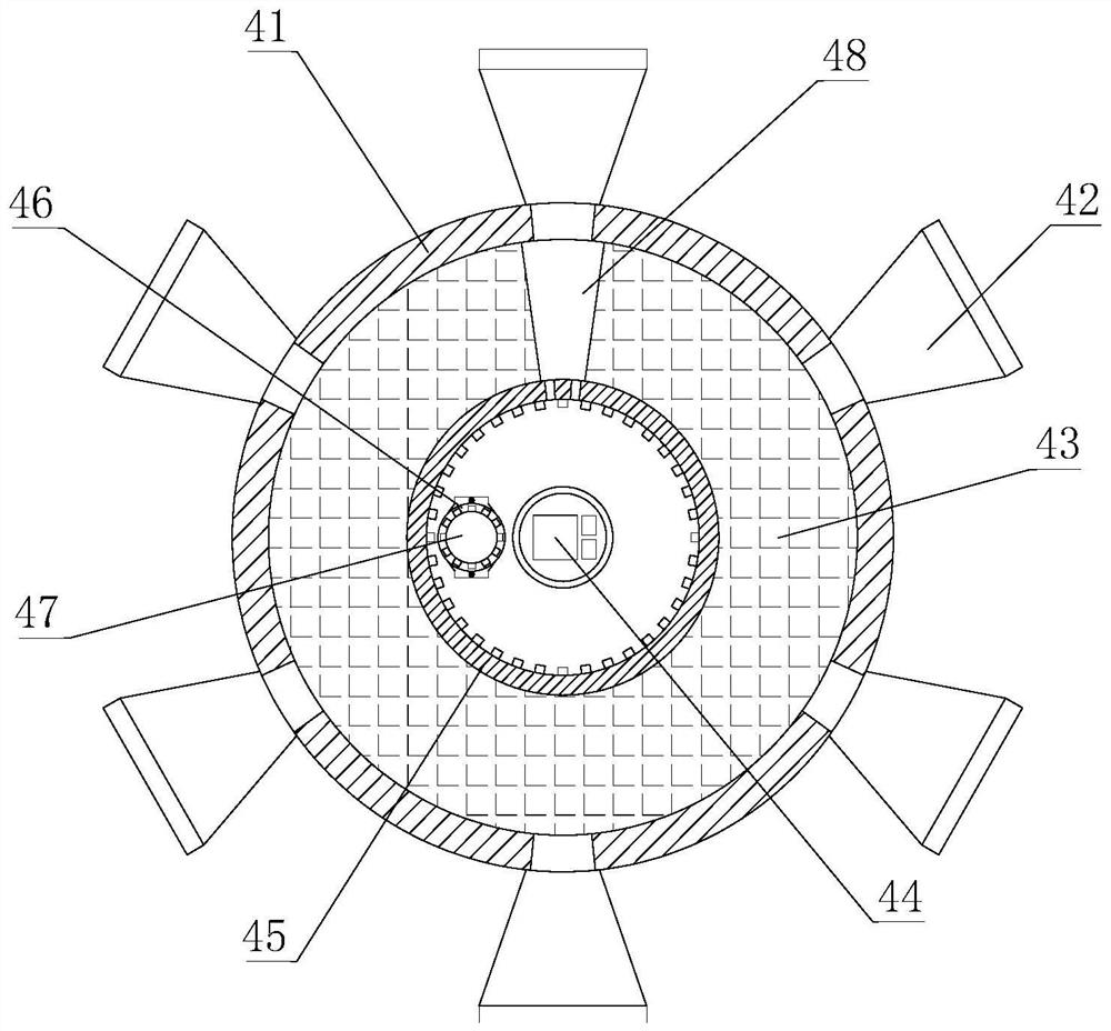
[0039] Such as Figure 1-7 As shown, on the basis of Embodiment 1, the present invention provides a technical solution: preferably, a stepping motor 46 is fixedly installed at the bottom of the cavity of the multi-directional monitoring box 41, and the output shaft of the stepping motor 46 is fixedly connected with an adjustable Gear 47, on the inwall of soundproof rotating disk 43, be fixedly connected with inner gear ring 45, the inner wall of inner gear ring 45 meshes with the outer wall of regulating gear 47, on the outer wall of inner gear ring 45, soundproof rotating disk 43, multi-directional monitoring box 41, all set There is a sound pass groove 48, and a fixed block 421 is fixedly installed on the inner wall of the sound collecting tube 42. The number of the fixed blocks 421 is set to two, and the back side of the fixed block 421 located at the front is movably inserted with a nylon filter cover 422, and the one located at the back The back side of the fixed block 42...
PUM
 Abstract
Description
Claims
Application Information
 - R&D
- Intellectual Property
- Life Sciences
- Materials
- Tech Scout
- Unparalleled Data Quality
- Higher Quality Content
- 60% Fewer Hallucinations
Browse by: Latest US Patents, China's latest patents, Technical Efficacy Thesaurus, Application Domain, Technology Topic, Popular Technical Reports.
© 2025 PatSnap. All rights reserved.Legal|Privacy policy|Modern Slavery Act Transparency Statement|Sitemap|About US| Contact US: help@patsnap.com


